
The main of the function of the Fuel Temperature Sensor is to correct for the decrease in fuel density as fuel temperature increases.
RAVE states this quite clearly so no real surprises....
The FT sensor is located at the rear of the engine in the fuel rail with the tip of the sensor inserted at least 10 mm into the fuel flow. This allows the sensor to respond correctly to changes in fuel density in relation to fuel temperature.
This function is handled by two maps:
Fuel Density Lower:
- EU2 - Map 62
- EU3 - Map 96
Fuel Density Upper:
- EU2 - Map 63
- EU3 - Map 97
These maps have Inject Quantity Request as the X axis, and Fuel Temperature as the Y axis, and output density corrected Inject Quantity.
The lower map is the density corrected IQ at 1000rpm while the upper map is the density corrected IQ at 4200rpm.
For engine speeds between these two points the density corrected IQ is interpolated between the upper and lower maps.
The Density Correction is effectively a four dimensional map - with IQ request, Fuel Temp and RPM as inputs, and the density corrected IQ as output.
The Fuel Density Compensation maps are located after the group of maps consisting of Driver Demand, Smoke Limiter, Torque Limiter, and immediately prior to the Duration Maps. Corrections applied here have a direct effect on the final inject duration.
Because the these maps act to modify the IQ request they have sometimes been identified as a performance enhancing map.
I'd strongly advise against taking this approach as changes to the lower map, and lower parts of the upper map will destroy the temperature -> density relationship and modify the relationship between the duration maps and DD, SL and TL.
Limiter function
A less obvious function of the Fuel Density maps is that they act as limiter on Inject Quantity.
This limiting function is an effect of the last column of the upper map which sets a maximum IQ at 4200rpm of 60mg/fire (stroke).
While the Fuel Density maps will output up to 100mg at 1000rpm, the effect of interpolation between the upper and lower maps means the maximum amount injected for 100mg request reduces as rpm increases.
The following plots show the interpolated value returned from the stock Fuel Density Compensation maps at various engine speeds.
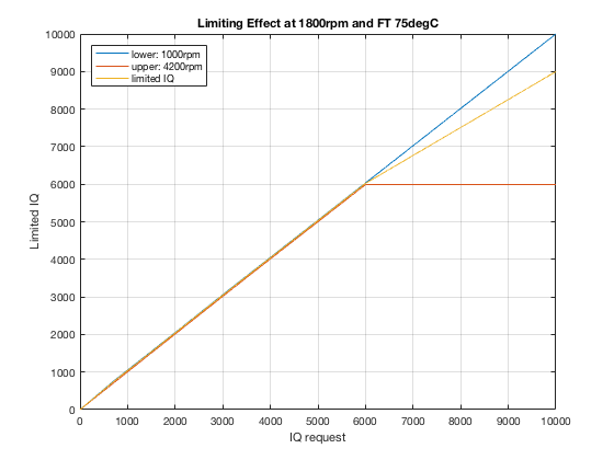
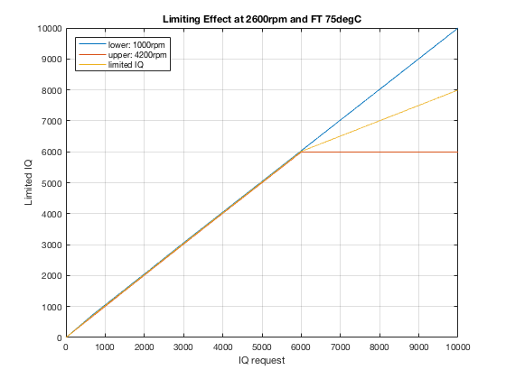
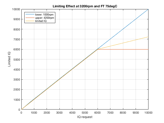
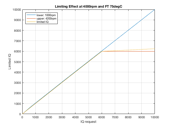
The "corner" at 60mg is quite obvious, and while it would have minor impact on a Stg 1 tune, once you start playing with 80-90mg/fire (or stroke) it becomes a major problem.
How to solve
Fortunately this is reasonably easy to rectify by changing the upper map. The lower map does not need any alteration.
The simplest solution is to alter the final header value from 6000 to 10000.
Then either use 10000 for each of the cell values in that column.
Alternatively use extrapolated values:
- 9769
- 9977
- 10057
A slightly safer approach is to set the header to your maximum IQ value,
and then interpolate the values between the current last column and 10000.
Current donor XDF's have been updated to include these maps. These are now being distributed in an archive of XDF's for all 49 variant-fuel map pairs listed in Nanocom Map Wizard.