
Garmen has posted up a Python script which at the moment allows the user to read out the "Nanocom Fuelling" parameters. github
The project uses a cheap serial programming interface based on the CP2102 USB to TTL converter plus some external circuitry to interface with comms levels. The trick is that the CP2012 needs to be reconfigured to suit the "non-standard" baud rates, and to allow sending a 0x00 byte with a period of exactly 25ms. It's a fairly neat trick.
Anyway Garmen's work prompted me to pull out a "dumb" OBD-II interface that I'd picked up a couple of years ago and thrown in the cupboard. Most OBD-II interfaces are based on the ELM-327 chip which basically does all the grunt work of managing the diagnostic connection and allows users to simply send OBD commands over a serial connection and read back the response.
A "dumb" interface is a USB to serial converter chip (usually a variant or clone of the FTDI FT232) and hardware to interface with the diagnostic port line levels. These are usually sold as something like "VAG-COM KKL USB Interface" - just google it... These require that the user application to handle all of the communications protocol details.
The interface I have has a cloned FT232BL. The complete lack of markings on the chip is the give away. But as the part cost $14.00AUS including postage it's hard to feel ripped off...
The nice thing about the FTDI chips is that they have a "Bit Bang" mode. This allows you to write a byte to the chip and it will hold that state until you write another byte. It's perfect for doing things like sending the 25ms wake-up message or bit-banging the 5 Baud initialisation sequence.
There are a couple of Python modules that allow access to these FTDI specific features. I'm using pyftdi.
As a rough example of how you do it...
#!/usr/bin/env python3

from pyftdi.ftdi import Ftdi
import time

HIGH = bytearray([0x01])
LOW = bytearray([0x00])
message = bytearray([0x81,0x13,0xF7,0x81])


uart = Ftdi()

uart.open(0x403, 0x6001)
uart.set_baudrate(10400)
uart.set_line_property(8, 1, 'N')

# Enable Bitbang Mode
uart.set_bitmode(0x01, 0x01)

# Set TX line high
uart.write_data(HIGH)


# Short sleeps in the loop seem to improve accuracy...
# Using time.sleep(.025) for the full delay is very jittery.
# time.perf_counter() can be used instead time.monotonic()
# requires Python 3.3 or later

start = time.monotonic()
while (time.monotonic() <= start + 0.35):
    time.sleep(0.01)

# Set TX line low
uart.write_data(LOW)

start = time.monotonic()
while (time.monotonic() <= start + 0.0245):
   time.sleep(0.00025)

# Set TX line high
uart.write_data(HIGH)

start = time.monotonic()
while (time.monotonic() <= start + 0.0245):
     time.sleep(0.00025)

# Disable Bitbang Mode
uart.set_bitmode(0x00, 0x00)

# Send serial message
uart.write_data(message)
Which should give you something like:
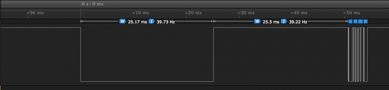
The ISO14230 spec states the total time for the wakeup time (Twup) should be 50ms +/- 1ms. This code gives Twup of 50.67ms, so is within spec.
As reference the Nanocom sets the line low for 26.54ms and then idles high for 118.9ms giving a Twup = 145.44ms. The Td5 ECU is pretty forgiving.