The 3.0 release of the XDFs includes two additional EU3 specific limiters.
Both limiters use ambient air temperature (AAT) as part of the calculation of the parameter value. This makes them slightly problematic as Nanocom omits this value from display and logs despite reading the data from the ECU.
Fortunately the calculations don’t seem overly sensitive to AAT so an estimation will likely suffice.
If you are estimating its worth understanding what AAT is...
AAT is not Ambient
While it’s been claimed in various places that the AAT sensor measures “ambient temperature” this somewhat misleading.
The AAT sensor is measuring air temperature inside the lid of the airbox and can be significantly higher than external ambient temperature.
The airbox temperature is effectively "pre-heated" by under bonnet temperatures, so engine, radiator, turbo, and even sun on the bonnet have an impact.

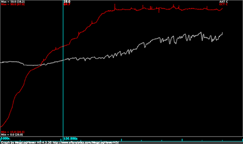
You can see from the logged data above that from a cold start AAT is reading around 26°C. As the engine and coolant warms up under bonnet temperatures increase and “ambient” temperature rises. AAT peaks at 38°C when the vehicle is idling at the end of the log. So in this example there is a 12 degree differential between AAT when the engine is cold and when the engine is hot and idling.

The other factor to consider is that increased air flow reduces the AAT reading.
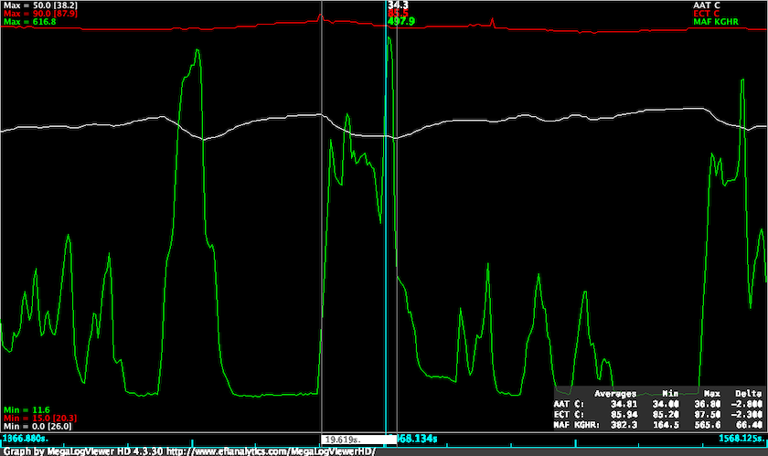
As can been seen in the zoomed section of the plot, there was a 2.8 degree drop in AAT when there is high flow through the airbox compared with the no load flow.
The take away is if you need to guesstimate assume AAT will be higher than ambient temperature by something like 10°C.
Over temp multiplier
This table is apparently used to limit fuelling to protect against excessive exhaust gas temperatures.
If you look at the table values you’ll see that the limiter has no influence below 3000rpm, nor when the Y axis parameter is at or below the minimum value.
The Y axis parameter is calculated from ambient pressure and temperature:
$$param = \frac{(AAT + 273.2) \cdot 50}{300} + \frac{25 \cdot 100}{AAP}$$
where AAT is °C and AAP is kPa.
If you were at 2000m where standard pressure is 81kPa, and you had an AAT reading at 35°C the limiter parameter would be:
$$param = \frac{(35 + 273.2) \cdot 50}{300} + \frac{25 \cdot 100}{81}$$
$$param = 82 = 0.82$$
This value is high enough to trigger limiting above 3500rpm.
The parameter calculation is roughly twice as sensitive to decrease in AAP as it is to increase in AAT. You'd need extreme AAT values in the range of 70-80°C to cause limiting at sea level.
Where this may become a factor is on high road passes - Stelvio Pass is 2757m ASL for example. At this altitude standard pressure is around 74kPa, so you'd be seeing limiting creeping in above 300rpm with 40°C AAT.
It is likely that this limiter will only rarely need to be touched, if ever.
Turbo Overspeed
The Turbo Overspeed limiter is a bit of a silent killer in the EU3 maps.
The limiter begins reducing fuel once operating conditions reach the equivalent of 1.5 bar boost and 680kghr MAF at sea level.
The exact limiting threshold will change with ambient pressure and temperature, manifold pressure, and mass air flow.
Working with the values in kPa, kg/hr and °C the main parameter calculation for the overspeed limiter is: $$ param = \frac{MAP + 0.0424 \cdot MAF \cdot \sqrt{AAT + 273.2}}{AAP}$$
The parameter calculation can be thought of having three main components:
- pressure ratio
- flow rate
- turbo speed constant
Pressure Ratio
This is a measure of input pressure (AAP) to output pressure (MAP). I’m ignoring the pressure drop caused by intercooler here, so:
$$pr =\frac{MAP}{AAP}$$ As an example lets look at pressure ratio required to produce 135kPa boost at AAP = 100kPa and 80kPa. $$pr = \frac{235}{100} = 2.35$$ $$pr = \frac{215}{80} = 2.69$$
You’ll see from the turbo map that turbine speed increases with pressure ratio. This means to produce the same output pressure turbine speed must increase as altitude increases.
Flow rate
The flow rate is determined as:
$$fr = \frac{MAF\times\sqrt{AAT K}}{AAP}$$
Assuming a temperature drop of 9.8°C per 1000m and 25°C ambient at sea level, and MAF = 500kg/hr.
At sea level: $$\frac{\sqrt(25+273.2)}{101} = \frac{17.27}{101} = 0.171$$ $$fr = 500 * 0.171 = 85.5$$
At 2000m ASL: $$\frac{\sqrt(5.4+273.2)}{101} = \frac{16.69}{80} = 0.209$$ $$fr = 500 * 0.209 = 104.5$$
A decrease in ambient pressure and turbo inlet temperature results in an increase in flow rate multiplier.
tb_speed_const
This is a scalar value set to 0.0424 in all fuel maps. This is incorrectly scaled in the 3.0 XDFs. The issue is fixed in 3.1 release.
Reassemble the components…
If we look at the parameter equation in terms of blocks we have this: $$param = pr + fr \times speedConst$$
So using the above values for sea level: $$param = 2.35 + 85.5 \times 0.0424 = 5.97$$ and 2000m: $$param = 2.69 + 104.5 \times 0.0424 = 7.13$$
The Overspeed limiter x-axis starts at 7.0, with no limiting applied below this parameter value.
Two it would appear that his calculation uses what are effectively the x and y axes of a turbo performance map to create a limiter that accounts for the effect of air density on turbine speed.
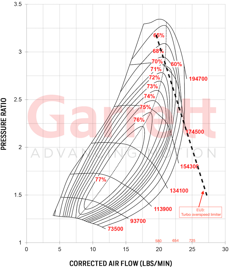
To further illustrate I’ve mapped the 7.0 parameter value for 680kg/hr MAF at sea level onto a GT2052S 52 trim performance map.

Note the figures in red above the x-axis are MAF in kg/hr.
Because this is a calculated parameter the only way to fully assess whether this limiter is actually impacting is to calculate using the above formula from log data.
This can be done with a spreadsheet app or using a calculated field in MegaLogViewerHD.
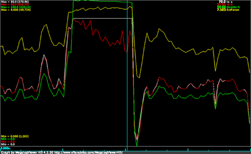
As a final illustration of the effect of this limiter, I’ll include a small segement of a log from a site donor who was having some major issues with a hybrid turbo and map levels over 250kPa.

The white trace is request IQ after Driver Demand and Torque/Smoke limiters.
The red trace is the IQ after application of the all system limiters including the Turbo Overspeed map.
The point at the cursor shows a 26% reduction in requested IQ corresponding to the 7.5 cell in the limiter map.
You can also see clearly that as the OS limiter parameter increases above 7.0 the IQ after all limiters reduces. MAP levels when limiting is occurring are around 250-260kPa.
The take away is simple:
If you are running boost above 250 kPa on an EU3 with a "new school" map this limiter is kicking your butt.
Adjusting the limiter
Rather than modifying the limiter table I would suggest altering the tb_speed_const.
Work out max Pressure Ratio at sea level - this MAP divided by AAP $$275kPa / 100kPa = 2.75$$
Subtract that from 7.0 to get your flow component. $$fc = 7.0 - 4.25$$
Work out your maximum MAF multiply and multiply by 0.1738 to get flow rate $$720 \times 0.1738 = 125$$
Divide the flow component by flow rate to find tb_speed_const: $$4.25 / 125 = 0.034$$
A note GT2052S turbo maps
The Garrett catalog and website list three different compressor trims for the stock GT2052S turbo: 48, 50 and 52. There are two maps available for the 52 trim version. The newest of these, which shows an extended range to a pressure ratio of 3.5, is on Garrett website. The others can be found in Garrett catalogs.
The problem here is that the Td5 uses the 54 trim compressor, and there is no publically avaliable map. The 52 trim will be the closest in performance but it will not be the same.
