Td5 Tuning

Axis Extends

Wednesday, December 28, 2016 - 09:00

Axis Extending the Smoke Limit map is the secret weapon of the new school remap.

When a value being looked up exceeds the maximum value for the axis the ECU uses the last value of the axis. In the case of an EU2 Auto the Airmass axis has a maximum value of 850mg/stroke. Any Airmass values above 850mg/stroke use this column to calculate the smoke limit IQ. This has the effect of gently rolling off the maximum AFR as Airmass climbs beyond the header value.

Looking at the stock IQ's of 850mg air, 48mg IQ at 2000rpm we can see this gives a maximum AFR of 17.7 to 1.
As Airmass increases, say to 1200mg/stroke, the same 48mg IQ limit applies giving a maximum AFR of 25:1.
Bumping the Max IQ to 57mg gives a AFR of 14.9:1 at 850mg/stroke, and 21:1 1200mg/stroke.
Due to the restriction of the airmass in the final column it becomes difficult to increase IQ without making the smoke.

The stock maps appear to select a final column value near the Airmass required at peak torque so the roll off in AFR occurs after this point.
Peak torque seems to occur around 2000-2500rpm so worth checking what Airmass you are making at full throttle at this point and then select the column header based on the airmass at peak torque.

As an example of how this works I've taken the last column of an EU2 Auto smoke map and calculated the existing AFR.
This is simply:

AFR = ( column header value /10) / (table value / 100)

The new values are calculated from the AFR and replacement column header value.

IQ = (New column header / AFR ) * 10

RPM 8500 9500 AFR
650 4000 4000 21.25 / 23.75
700 3000 3353 28.33
1000 3200 3576 26.56
1200 3600 4023 23.61
1500 4800 5365 17.71
1800 4800 5365 17.71
2000 4800 5365 17.71
2700 4800 5365 17.71
3000 4800 5365 17.71
3500 4400 4918 19.32
4200 4400 4918 19.32
4900 3600 4024 23.61

The main tables that need this kind of treatment are the Smoke maps as the higher airmass values in the axis headers allow increased fuel inject amounts while avoiding setting AFR to a level that results in excessive smoke.

Injector Duration Maps

Tuesday, December 20, 2016 - 08:15

The "Old School" mod of choice..

Modifications to the inject duration maps are a key element of "old school" tuning.
The main reason this is done is because the injector open times looked from these maps are not modified - excepting for adjustments for injector performance codes - before being sent to the injector control code. If a tuner modifies these maps there are no problems with "unknown" limiters restricting the requested IQ, and there is no need to account for map variations between Defender, D2 Manual or D2 Auto. It makes life very simple.

The inject duration maps come in two variations - one for EU2 motors with lower pressure/larger fuel droplet injectors and one for EU3 motors with high pressure/smaller fuel droplet injectors. In other words a ROW Defender 110 and Euro D2 with Auto running the same variation of the motor/injectors have identical inject duration maps. Basically these maps are calibration for the behaviour EU2 and EU3 injectors and how droplet size of the injected fuel effects the burn characteristics, and translate a request for a specific Inject Quantity into the opening time required to deliver the requested amount of fuel.

Duration Map axes

  • X-axis: requested IQ mg/stroke
  • Y-axis: Engine speed (RPM)
  • Z-axis: Injector duration (ms)

Map Identification

EU2

  • Map 64: Inject Duration <= 0 degrees advance
  • Map 65: Inject Duration - 5 degrees advance
  • Map 66: Inject Duration >= 10 degrees advance

EU3

  • Map 98: Inject Duration <= 0 degrees advance
  • Map 99: Inject Duration - 5 degrees advance
  • Map 100: Inject Duration - 10 degrees advance
  • Map 101: Inject Duration >= 25 degrees advance

The Duration maps are selected on the basis of overall Start of Injection timing. The maps define duration at 0, 5, 10 and 25 (EU3 only) degree advance with the ECU interpolating values between the maps for intermediate values.
In effect the 3 or 4 individual maps create a 4 dimensional table with advance as the 4th dimension.

Duration Maps as Calibration

The idea that the duration maps are calibrated to deliver the correct amount of fuel for a specific Inject Quantity request is a fundamental idea to "new school" tuning. The Driver Demand, Smoke Limiter and Torque Limiter IQ values are set on the basis that if the ECU requests 35mg of fuel at 2500rpm, the injectors are going to deliver 35mg. Altering the duration maps as a method of tuning destroys that relationship, in that a request for 35mg at 2500rpm might deliver 40.25mg by increasing the length of time the injector remains open.

I should note that the calibration maps are not an exact linear relationship of IQ request to duration. Duration values are influenced by the behaviour of the combustion chamber, scavenging of exhaust gases and the fuel droplet size so seem to incorporate a degree of fitting to the engine design.

Fortunately with the EU2 motors the duration maps extend well past the normal operating range, so it's relatively straight forward to get away without adjusting the duration maps. The EU3 motors present a far greater challenge as the duration maps are truncated to just above the expected operating maximum of approximately 50-55.00mg/stroke, so need to be modified to extend the range of usable IQs.

The EU3 mods I have in mind are currently untested and will require at very least a Wideband O2 sensor to verify "what you request is what you get". In general terms the idea is that the upper column needs to be altered by extrapolating based on the increment and value increases present in the EU2 maps. Again the idea is not to make broadscale tuning mods, but to allow the injectors to deliver the amount of fuel requested.

Difference between EU2 and EU3 duration maps

Due to the differences in table breakpoints (axis values) it's a bit tricky to compare the EU2 and EU3 duration maps. By interpolating the values from the EU2 duration maps to match those of the EU3 maps it's possible to get a sense of how different the Duration maps actually are.

The following image shows the difference in cell values between the EU3 "0 degree" duration map and the EU2 "0 degree" duration, which has been interpolated to same IQ Request values. The last two columns of EU2 map are repeated to approximate the EU3 final column.

Interpolating the EU2 durations for the 70mg IQ request column gives an indication of where EU3 duration would fall if the final column did not repeat the 50mg IQ request. The EU3 durations are shown in red, and EU2 interpolation in light grey. It's apparent that across most of the map the EU2 duration values are slightly higher. The most obvious exception is the low rpm range.

E2 and EU3 overlaid

The idea is to correct the last column of the EU3 maps to remove the limiting LR has designed in by repeating the 50mg column values. This limiting is not present in the EU2 maps so interpolating based on the curve of the EU2 maps in this region gives us an fair approximation of correct values.

The image below shows the type of correction of the last column required to make the "new school" maps work on EU3 motors.

Corrected EU3 duration

The end goal is to have the injectors deliver fuelling that matches the IQ requested.

Airmass

Sunday, December 4, 2016 - 17:30

Note: There was a bit of doubt about the airmass units on my part. This has now been resolved and milligrams/stroke is the winner.

The first "secret' of the Td5 engine maps is that nothing is quite what it seems at first glance.

If you look at the live data from a Nanocom you are presented with individual sensor readings for MAF and MAP, and the assumption is usually the engine is using MAF for fuelling and the MAP readings for boost. In fact, the reality is a bit more complex.

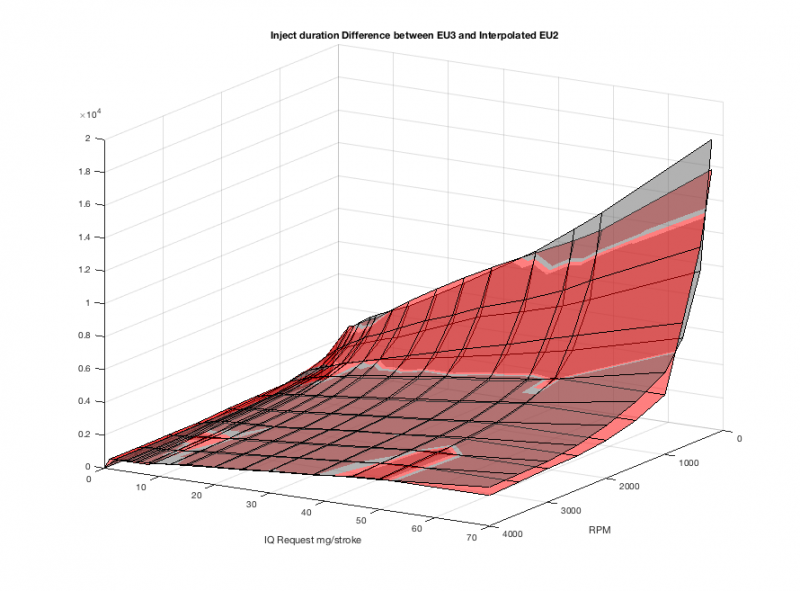
EU2 motors use data from the MAP and IAT sensors to calculate the airmass in milligrams within each cylinder on each intake stroke (mg/stroke).

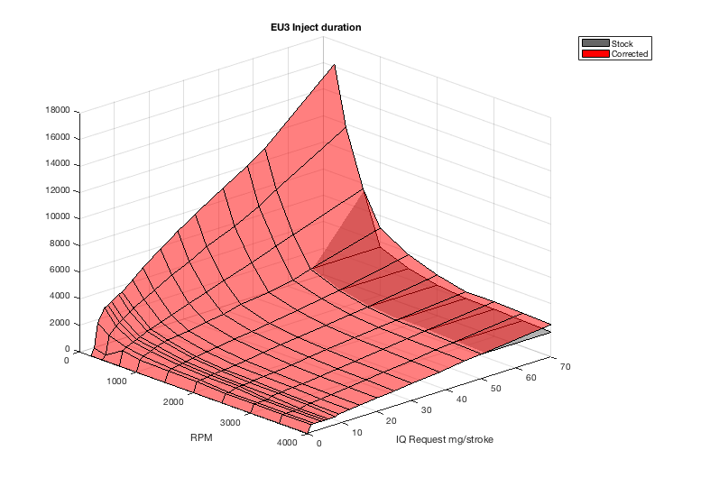
For EU3 motors the data from the MAF sensor and the Engine Speed in RPM are used to determine the airmass in milligrams within each cylinder on each intake stroke (mg/stroke). As a backup EU3 motors will fail over to MAP/IAT based calculations if the MAF is outside a specific range but more on this later.

The airmass figures indicates is the mass of air within the cylinder at the end of the intake stroke. This is a critical piece of information for the engine as the amount of fuel injected depends on a combination of the amount of air within the cylinder and the speed of the engine

Unfortunately the Nanocom does not give access to the live data for the Airmass parameter, so the only option is to use the MAP/IAT and MAF/RPM data to calculate the airmass value. Strictly speaking airmass value based on the MAF reading is not calculated - Mass Air Flow is divided down to reflect the amount of air drawn into the cylinder on each intake stroke.

I've posted up the math to calculate airmass to several forums as a method of comparing the MAP and MAF readings for diagnostic but the significance has been elided. I'll run through the calculations again before moving on.

It's important to note that the Nanocom alters the values reported by the ECU to more familiar units. This is fine for some purposes but it does tend to obscure the relationship with engine map parameters. I've added multipliers and conversion from deg C to Kelvin (+ 273.2) as necessary.

Speed-Density: Airmass from MAP and IAT

The calculation used for this conversion is based on the Ideal Gas Law, which can be used to calculate the amount of air present in the cylinder given the volume, absolute pressure and inlet air temperature. This method is commonly known as speed-density, and RAVE makes passing reference to this in the Td5 ECU section of the D2 workshop manual.

The formula for the Ideal Gas Law is PV = nRT

  • P is absolute pressure
  • V is volume in litres
  • n is the amount of substance of a gas - also known molar mass. For air this is approx. 28.97g/mole
  • R is the universal gas constant
  • T is absolute temperature in Kelvin.

When all the parameters are known - as in the case of the ECU - the formula can be rewritten as`

n = PV/RT

Airmass in grams can then be found by multiplying n by n(air).

The Td5 ECU applies this method to calculate Airmass based on the MAP and IAT readings:

airmass = (MAP * Cylinder Volume in cc * Molar Mass air (g/mole)) / (IAT(K) * R)

A point of clarification on the ECU units. The MC68336 processor used in the ECU does not provide hardware support for floating point math, making working with decimal fraction extremely slow. To keep the calculations fast integer math is used, and the number scaled to give the required precision. If accuracy to 1 decimal place is required the number is multiplied by 10. The value for R requires three decimal places accuracy and is multiplied by 1000.

The internal values used by the ECU are:

  • MAP = kPa * 100 (or milliBar * 10)
  • IAT = Kelvin * 10
  • Cyl Volume = 498
  • n(air) = 28980
  • R = 8314

To use this with Nanocom logs I substitute the ECU constants used for the fixed elements, and scale to match the ECU internal values for MAP and IAT. The Nanocom alters the raw log values to a more user friendly format, so this requires converting IAT from Celsius back to Kelvin, and multiplying MAP by 100.

airmass = (MAP * 100 * 498 * 28980) / ((IAT+273.2) * 10 * 8314)
or
airmass = (MAP * 10 * 498 * 28980) / (IAT+273.2) * 8314)

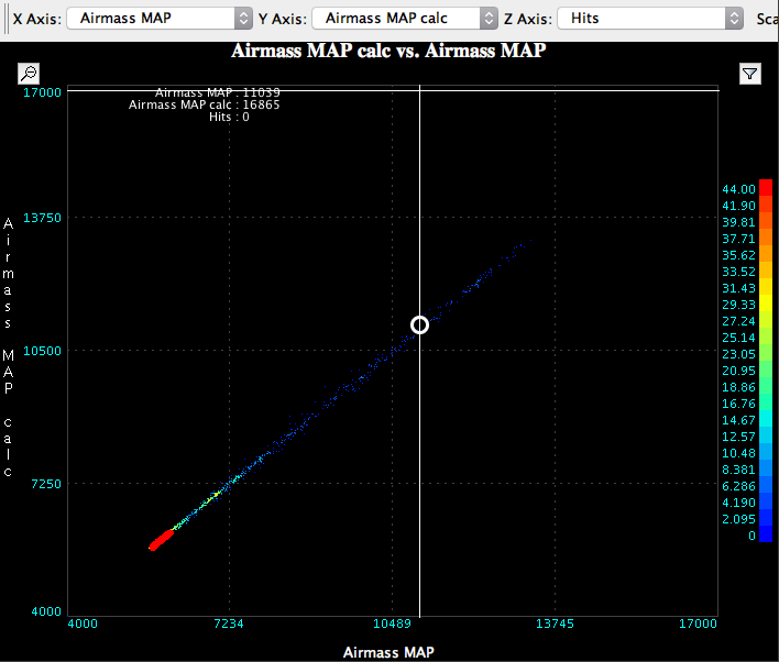
The value is close to the ECU calculated value but suffers from a small amount of time smearing due to the engine conditions changing between sensor requests. As can be seen below the relationship between ECU values and the value calculated from MAP and IAT is pretty close, as shown by the straight 45 degree line.

MAP Airmass

MAF and RPM

The MAF airmass calculation is simplified because the MAF reading is already provides the airmass entering the engine given in kg/Hr. Conversion from kg/hr -> g/min is done by multiplying by 1000 and dividing by 60. The intake stroke of each cylinder occur once every 2 revolutions, so the airmass is divided by 5/2 to determine the amount per cylinder. The ECU code combines these to simplify calculation:

33.333 = (1000 * 2) / 60

The final code used in all variants of the Td5 ECU is:

airmass = (MAF * 33333) / (RPM * 5)

Note that the decimal point of the constant is shifted right three places to retain precision in integer math. The ECU representation of the MAF vale has it's decimal point shifted one place to the right. This is significant when reading the ECU maps as the map values use these fixed point numbers.

To confirm the magnitude of the units, lets apply this to the Nanocom values at a typical idle reading of 60kgHr/ 760rpm.

airmass(g) = 60 * 33.333 / 760 *5 airmass = 0.5263g or 526.3mg

And at 680kg/Hr/ 3500rpm airmass = 1.2952g or 1295.2mg

Referring to 0.5623g airmass feels pretty clumsy, so my preference is to use mg.

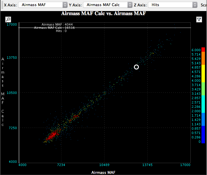
Looking at log data the time scatter is far more evident in the MAF airmass from the same log data as the MAP airmass. This is evident in the spread of values above and below a 45 degree line.

MAF Airmass

Bonus diagnostic content.

Because we are calculating two values measuring the same quantity, it is possible to check sensor health by comparing the two readings using a scatter plot. If the sensors are behaving correctly there is a linear relationship between the airmass values. If one of the sensors is misreading you tend to see distinct curvature or complete breakdown of the relationship.

Pages

randomness