Given my recent posts about bugs in the Nanocom's handling of injector idle codes I thought I'd pull together some background information.
Codes
The documentation on injector codes indicates that the injector idle letter codes map to numeric values.
These numeric values are 0-based indexes for idle adjust tables which are located in the fuel map.
Each idle code maps to an adjustment ranging from -0.075ms to +0.075ms in EU2 maps, and -0.047ms to +0.047ms in EU3 maps.
ECU Hardware
At the most basic level the MSB and NNN have different limitations on the value that can be saved.
The MSB masks the values sent by the diagnostic tool by performing the equivalent of modulo 4 of the value sent by the diagnostic tool.
The effect is that if you send an idle code of 5 to an MSB it saves 1 to eeprom.
The NNN masks values with the equivalent of modulo 16, meaning it can save values In the range of 0-15 to eeprom.
10P maps and NNN
Regardless of whether running on MSB or NNN hardware 10P (EU2) maps mask the injector code to modulo 4.
This snippet in python demonstrates the effect. % is the modulo operator.
mask = 4
for i in range(9):
    print(f"{i} modulo {mask} = {i % mask}")

"""
Output:
0 modulo 4 = 0
1 modulo 4 = 1
2 modulo 4 = 2
3 modulo 4 = 3
4 modulo 4 = 0
5 modulo 4 = 1
6 modulo 4 = 2
7 modulo 4 = 3
8 modulo 4 = 0
"""
So while the diagnostic code will allow programming of 15P idle codes to an NNN running a 10P map, the map will use the 0-3 10P coding.
The effect is that the 10P coding is repeated for the higher 15P codes...
15P: 1, 2, 3, 4, 5, 6, 7, 8
10P: 1, 2, 3, 0, 1, 2, 3, 0
Code for the map, not the ECU
It should be clear from the above that injector codes are interpreted based on the map being run rather than "earlier" or "later" ECU's.
The ideal here is to use the correct map for the injector type and engine, and set the idle codes accordingly.
Idle adjust tables
I mentioned earlier that the idle codes are index values.
So let's look at what that means in practice.
10P idle
I briefly had the hidden 10P idle map defined in the XDF's but removed as it was causing significant confusion.
For reference this is what the idle adjust table looks like:
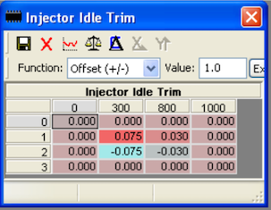
The x-axis is rpm, and y-axis is the numerical idle code for black/blue top injectors.
What we can see from this is that idle codes 0 and 3 are both 0ms adjustment across the board.
So the equivalence of A = 0,3 makes perfect sense.
Index 1 is a positive adjustment, ranging from 0.075ms at 300rpm, 0.030ms at 800rpm and 0ms at 1000rpm.
Index 2 is a negative adjustment which is the mirror of Index 1: - 0.075ms at 300rpm, -0.030ms at 800rpm and 0ms at 1000rpm.
Interpolating the values indicates that the adjustment at 760rpm is +/- 0.033 ms depending on code 1 or 2.
You'll notice that In 10P maps idle adjustment has no effect above 1000rpm.
15P idle
The 15P maps have the idle adjust map defined as a standard table.

This is obviously very different to the 10P map. The rpm axis is gone and there are now 10 columns with indexes in the range of 0-9.
Looking at the time adjustments in each column it becomes apparent that 0 and 9 are the equivalent of rows 0 and 3 in the 10P map.
With this in mind it should be fairly obvious why the equivalence of M = 0, 8 looked highly questionable. It's simply not a valid statement to say 0ms is the same as -0.047ms.
The idle codes with values roughly follow the arrangement of the 10P table.
Columns 1-4 contain positive adjustments, 5-8 contain negative adjustments which mirror the first 4 values.
10P codes 1 and 2 roughly align with 15P codes 2 and 7 respectively.
This should give a clue how it would be possible to code injectors when running a 15P map on 10P hardware:
- "B" is equivalent to "F"
- "C" is equivalent to "L"
I'll update further when I have some time, but this should give some basis for understanding the issues behind the injector coding bugs I've described.


