Td5 Datalogger updates

Sunday, June 11, 2017 - 08:00

I've come to something of a Catch 22 where I need detailed logging to properly document and verify the waste gate modulator, and the code that handles torque reduction requests from the auto gear box before I can post details of the maps. On the other hand, if I work on the datalogger nothing much happens on the website.

The combination of changes to the Microchip tool chain which caused issues with my old code, a failed hard drive which lead to the discovery that the Microchip peripheral library installer does not work on current versions of macOS, and the need for a rethink and rewrite has meant the datalogger has been out of action since late December.

When I was playing around with the VAGCOM adapter and Python earlier in the year I had ported//rewritten part of my C code and found that using a publish and subscribe framework solved a few of the issues I'd run into. As a result of that little "ah ha" moment and the hassle of dealing with the Microchip libraries I've been working on writing and unit testing peripheral drivers and a publish & subscribe framework in C.

Over the past few weeks I've been progressively bolting together the code that manages the communications with the Td5 ECU.

The way I've decided to approach this is to look at the ISO14230 docs and build a module that handles the startCommuncations, sendData and stopCommunications commands as the base of the logger/interface. That section is now working quite well and at this stage only requires some additional error handling to deal with cases where the ECU response times out mid-message.

From that base I've been working on adding a command interface and USB interface. The idea is to provide a basic set of ELM-like AT commands to configure the settings from default. The current defaults for "pass through" operation are set to connect to a Td5 ECU in manufacturer specific diagnostic mode - Testbook diagnostics in other words.

In practice this means you can hook up the interface and send requests without worrying about the underlying communications protocols. This is similar to how the ELM327 operates.

This is a short demo of the pass through mode, operating over a serial usb connection. The delay between hitting return on the "21 01" command and the response includes the time taken to connect and authenticate to the ECU.

AAP/AAT sensor swapping

Friday, April 7, 2017 - 12:15

This is a fairly niche modification.

EU2 and EU3 engines are fitted with significantly different airbox sensors.

The EU2 uses a three wire Ambient Air Pressure sensor, while the EU3 uses a four wire Ambient Air Pressure/Ambient Air Temp sensor.

The curve of the AAP portions of the two sensors are different and require different parameters to give the correct reading.

Without adjusting the parameters there is a misread of around 10kPa. You'll get an over-read ( -700 m altitude) with EU2 AAP + EU3 tune, and under read (+700m altitude) with EU3 AAP + EU2 tune.

The problem is not so bad with EU2 AAP + EU3 tune as the engine assumes higher air density in some correction maps and will INCREASE injected fuel and give a 0.1 bar increase in the boost limit. The boost level is MAP - AAP so reducing AAP by 0.1 results in boost levels 0.1 higher than the would be with correct setup. I suspect this is why you often hear the comment that an EU3 tune drives better that the correct EU2 tune.

If you've addressed the issue by installing a 4-wire sensor - replace airbox lid, sensor and run an extra wire back to the ECU - the problem occurs when you want to run an EU2 map on the motor. The under-read means the ECU uses corrections which reduce the fuelling plus the boost limit is reduced by 0.1 bar. It guarantees bad performance.

The fix is in

The way to fix this problem is to use the correct parameters for the AAP you have installed. Search for the values for the base map and replace with values for the sensor you are using.

EU3 - 4 wire sensor
multiplier: 13171 ( 0x3373 )
offset: 267 ( 0x010B )

EU2 - 3 wire sensor
multiplier: 10410 ( 0x28AA )
offset: 1227 ( 0x04CB )

It's not too hard to find these values with a hex editor as I think they are fairly unique. As a rough guide they are somewhere around an offset of 0x6A0 from the start of the fuel map. In a Nanocom .map the fuel map always begins at 0x19010.

The donor-ware XDF's now have a patch that swaps the values. It's a bit rough as it shows a stock EU3 tune as being patched, so installing the EU2 parameters requires "reversing" the patch.

Td5 NNN ECU "Base" Code

Sunday, March 5, 2017 - 14:15

NOTE: This post has been updated to reflect that the driver chips NOT related to injector control. Rather these chips are used for things like PWM outputs to the instrument panel.

One of the very early posts one this site shows a diagram of the firmware layout used on the Td5 NNN ECU's.

The portion of memory located between addresses 0x0000 - 0xFFFF was cryptically called "ECU Base Code", with the note that this is not touched during Nanocom .map uploads.

The "Base" code is possibly better described as management or boot loader code. In normal usage the main function it performs is basic setup of the ECU hardware, verifying that certain check points are present in the Variant and Fuel maps, then running the variant map code if everything correct.

The secondary function of the management code is to provide support for factory programming of the ECU. Without a variant or fuel map installed the ECU will boot into a special diagnostic mode that provides access to the functions need to upload .map files, program injector codes, synchronise with the BCU immobiliser, and set the throttle pedal type. I assume this mode would have been used on the production line to program new ECU after installation into a vehicle.

The management code is identical across all the NNN ECU's with two minor differences.

The first difference is the code identifier. Like engine maps each variant management has a unique identifier. The second difference is the ECU hardware code, which reflects the well know NNN numbering. So the thbtp001 ecu code has the indentifer NNN000120, whereas the thbtp005 has the identifier NNN500250.

The complete list is:

NNN000120: thbtp001
NNN000130: thbtp002
NNN500020: thbtp003
NNN500030: thbtp004
NNN500250: thbtp005

If you are simply uploading .map files using a diagnostic tool you don't need to worry about this as the management code is not touched even if you brick the ECU.

Where you can run into problems is if you upload a complete .bin file from a different ECU type.

One of the differences between the NNN000xxx and NNN500xxx ECU's is that the power driver chips used to control the injectors pwm output and some switches were changed from Intersil HIP0060 to Infineon TLE6220GP parts. While both types of chips use Serial Peripheral Interface bus to communicate with the MCU the format of the messages and the representation of faults differs.

The ECU code uses the identifier from the management code to determine which driver chip is present.

So if you fit a .bin from a NNN000120 to a NNN500020 or NNN500250 for example the Variant code will read the NNN000120 identifier and use the code for the HIP0060 driver chip, rather than the TLE6220GP.

What makes this problematic is that one chip arranges it's fault codes:

A_OverTemp, B_OverTemp, C_OverTemp, D_OverTemp,  A_OpenLoad, B_OpenLoad, C_OpenLoad, D_OpenLoad

with a value of 1 signalling a fault.

The other uses:

A_bit1, A_bit2, B_bit1, B_bit2, C_bit1, C_bit2, D_bit1, B_bit2

If both bit1 and bit2 are set to value of 1 the channel is operating normally, and if both are set to zero there is a "short to ground" fault present.

This means if you send the diagnostic bits from a HIP0600 showing no faults (all zeros) to an ECU configured for a TLE6220GP the best you can hope for is "short to ground" faults on all channels.

The injector fault checking is called in the main loop of the ECU code and it's potentially updated every 10 milliseconds or so. I haven't been able to confirm how this impacts general running, but I've been speaking to someone who has had ongoing issues with poor starting who appears to be running NNN000120 management code on an NNN500250 so it seems fairly likely this is related.

Anyway, it's something to be aware of...

Using an XDF with Td5 engine maps...

Thursday, March 2, 2017 - 06:45

There are a couple of little tricks to loading up the Tuner Pro defintions so thought I'd make a quick post on the procedure.
You'll have to excuse the "retro" Win XP look n feel. I'm running a Windows virtual machine under macOS and XP does the job without too much bloat.

1. Open a file to edit.

Use File >> Open Bin to open the file to edit.
For nanocom .map file select "All Files" as the file type.

Open dialog

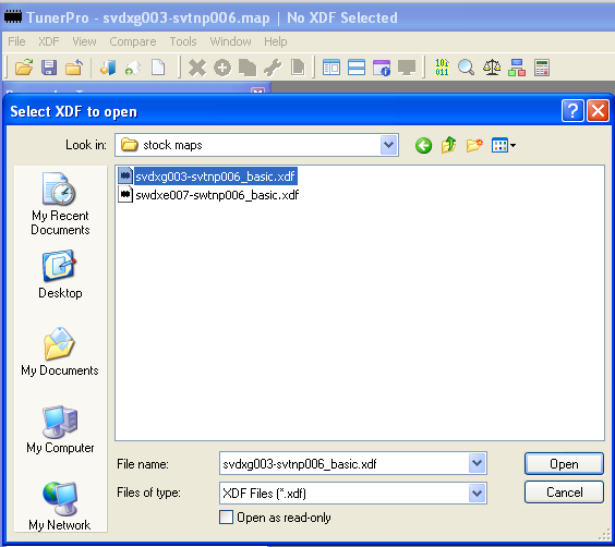
2. Open the XDF

Use XDF >> Select XDF to open the appropriate XDF file.

Open XDF

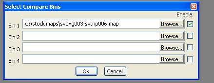
3. Add Compare Bin

Use Compare >> Load Compare Bins... to load one or more compare bins.

Load compare bins

With a compare bin loaded you can use the "Show compare difference" and "Show compare bin data".

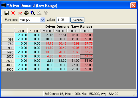
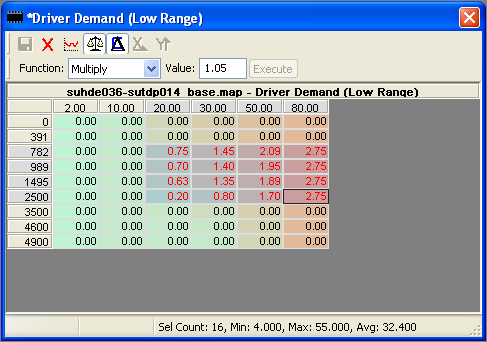
  • Using a random mod to illustrate, select a range of cells and multiply by 1.05
    Random mod

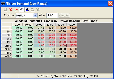
  • Clicking the "Scales" icon gives "Show compare bin data" - table values from the Compare Bin.
    compare bin data

  • With "Show compare bin data" on, clicking "Show compare difference" shows the difference between the map being edited and the compare bin.
    compare difference

If you find yourself having to load the same base file and xdf every time you start Tuner Pro, go into Tools >> Preferences and under the "Genera"l tab enable the two options to load the last used file at startup.

Footnote

I'm offering what I describe as a "basic" XDF as donor-ware. These have a bit more detail on tables than Td5MapEditor, have some unit converted to more human friendly representations, and allow direct editing on MAP and Boost limits using the GUI.
The "deal" is anyone who makes a donation will receive an XDF of their choice. How much you donate is entirely up to you.

Live data, at last.

Wednesday, April 6, 2016 - 19:45

The logging to sd card is proving to be a bit of a case of one step forward, two steps back.

Most of the the difficulty has resulted from the decision to make the logging "user" configurable.

Rather than the fixed set of logged parameters that Td5 owners are familiar with from the Nanocom, one of the goals is to allow granular parameter logging . Not all data is available as a single request, but for those that are it's possible to log at more than 10 times per second giving very detailed snapshot of sensor performance.

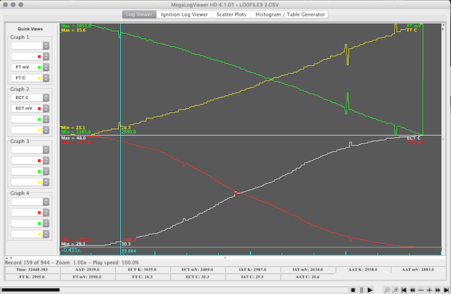
The screen grab below shows some of the data captured on a short 4 minute run around the block. The top graph is Fuel Temp in C and FT sensor voltage. The lower graph is Engine Coolant Temp and ECT sensor voltage. These are being sampled at slightly more than 4 times per second vs the Nanocom sample time of once every 1.25 seconds.

The log viewer app I'm using is MegaLogViewer HD . The big plus of this over the free Nanocom log viewers is that it's very flexible and allows user defined calculations based on the log data.

Pages

randomness