Map Finder

Wednesday, April 15, 2020 - 17:45

The "Stay at Home" directive from local authorities has given me time to dig out a couple of projects I'd put on the backburner last year.

I'd run into problems building the "Map Finder" app for distribution when I was working on it previously. Today I dusted the project off and finally sorted out the build issues.

The app uses a cross platform gui for python called Kivy that theoretically allows an application to run on macOS, Windows, Linux, iOS and Android.

"Map Finder" uses a database back end to display and filter a listing of engine maps based on a set of criteria - Vehicle, Engine, Wheelbase or Transmission and finally Market. The idea was/is that this will end up as part of a cross platform tool for generating and manipulating Td5 engine map formats.

EU3 Specific Limiters

Friday, September 13, 2019 - 08:45

The 3.0 release of the XDFs includes two additional EU3 specific limiters. Both limiters use ambient air temperature (AAT) as part of the calculation of the parameter value. This makes them slightly problematic as Nanocom omits this value from display and logs despite reading the data from the ECU. Fortunately the calculations don’t seem overly sensitive to AAT so an estimation will likely suffice.
If you are estimating its worth understanding what AAT is...

AAT is not Ambient

While it’s been claimed in various places that the AAT sensor measures “ambient temperature” this somewhat misleading. The AAT sensor is measuring air temperature inside the lid of the airbox and can be significantly higher than external ambient temperature.
The airbox temperature is effectively "pre-heated" by under bonnet temperatures, so engine, radiator, turbo, and even sun on the bonnet have an impact.
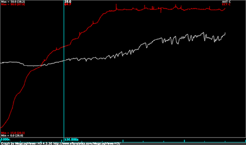
AAT and ECT

You can see from the logged data above that from a cold start AAT is reading around 26°C. As the engine and coolant warms up under bonnet temperatures increase and “ambient” temperature rises. AAT peaks at 38°C when the vehicle is idling at the end of the log. So in this example there is a 12 degree differential between AAT when the engine is cold and when the engine is hot and idling.
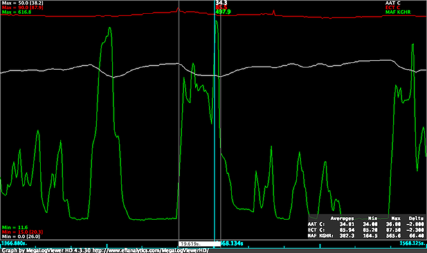
MAF, AAT and ECT

The other factor to consider is that increased air flow reduces the AAT reading.
As can been seen in the zoomed section of the plot, there was a 2.8 degree drop in AAT when there is high flow through the airbox compared with the no load flow.

The take away is if you need to guesstimate assume AAT will be higher than ambient temperature by something like 10°C.

Over temp multiplier

This table is apparently used to limit fuelling to protect against excessive exhaust gas temperatures.

If you look at the table values you’ll see that the limiter has no influence below 3000rpm, nor when the Y axis parameter is at or below the minimum value.

The Y axis parameter is calculated from ambient pressure and temperature:
$$param = \frac{(AAT + 273.2) \cdot 50}{300} + \frac{25 \cdot 100}{AAP}$$

where AAT is °C and AAP is kPa.

If you were at 2000m where standard pressure is 81kPa, and you had an AAT reading at 35°C the limiter parameter would be: $$param = \frac{(35 + 273.2) \cdot 50}{300} + \frac{25 \cdot 100}{81}$$
$$param = 82 = 0.82$$

This value is high enough to trigger limiting above 3500rpm.

The parameter calculation is roughly twice as sensitive to decrease in AAP as it is to increase in AAT. You'd need extreme AAT values in the range of 70-80°C to cause limiting at sea level.

Where this may become a factor is on high road passes - Stelvio Pass is 2757m ASL for example. At this altitude standard pressure is around 74kPa, so you'd be seeing limiting creeping in above 300rpm with 40°C AAT.

It is likely that this limiter will only rarely need to be touched, if ever.

Turbo Overspeed

The Turbo Overspeed limiter is a bit of a silent killer in the EU3 maps.

The limiter begins reducing fuel once operating conditions reach the equivalent of 1.5 bar boost and 680kghr MAF at sea level.

The exact limiting threshold will change with ambient pressure and temperature, manifold pressure, and mass air flow.

Working with the values in kPa, kg/hr and °C the main parameter calculation for the overspeed limiter is: $$ param = \frac{MAP + 0.0424 \cdot MAF \cdot \sqrt{AAT + 273.2}}{AAP}$$

The parameter calculation can be thought of having three main components:

  1. pressure ratio
  2. flow rate
  3. turbo speed constant

Pressure Ratio

This is a measure of input pressure (AAP) to output pressure (MAP). I’m ignoring the pressure drop caused by intercooler here, so:

$$pr =\frac{MAP}{AAP}$$ As an example lets look at pressure ratio required to produce 135kPa boost at AAP = 100kPa and 80kPa. $$pr = \frac{235}{100} = 2.35$$ $$pr = \frac{215}{80} = 2.69$$

You’ll see from the turbo map that turbine speed increases with pressure ratio. This means to produce the same output pressure turbine speed must increase as altitude increases.

Flow rate

The flow rate is determined as:

$$fr = \frac{MAF\times\sqrt{AAT K}}{AAP}$$

Assuming a temperature drop of 9.8°C per 1000m and 25°C ambient at sea level, and MAF = 500kg/hr.

At sea level: $$\frac{\sqrt(25+273.2)}{101} = \frac{17.27}{101} = 0.171$$ $$fr = 500 * 0.171 = 85.5$$

At 2000m ASL: $$\frac{\sqrt(5.4+273.2)}{101} = \frac{16.69}{80} = 0.209$$ $$fr = 500 * 0.209 = 104.5$$

A decrease in ambient pressure and turbo inlet temperature results in an increase in flow rate multiplier.

tb_speed_const

This is a scalar value set to 0.0424 in all fuel maps. This is incorrectly scaled in the 3.0 XDFs. The issue is fixed in 3.1 release.

Reassemble the components…

If we look at the parameter equation in terms of blocks we have this: $$param = pr + fr \times speedConst$$

So using the above values for sea level: $$param = 2.35 + 85.5 \times 0.0424 = 5.97$$ and 2000m: $$param = 2.69 + 104.5 \times 0.0424 = 7.13$$

The Overspeed limiter x-axis starts at 7.0, with no limiting applied below this parameter value.

Two it would appear that his calculation uses what are effectively the x and y axes of a turbo performance map to create a limiter that accounts for the effect of air density on turbine speed.

To further illustrate I’ve mapped the 7.0 parameter value for 680kg/hr MAF at sea level onto a GT2052S 52 trim performance map.
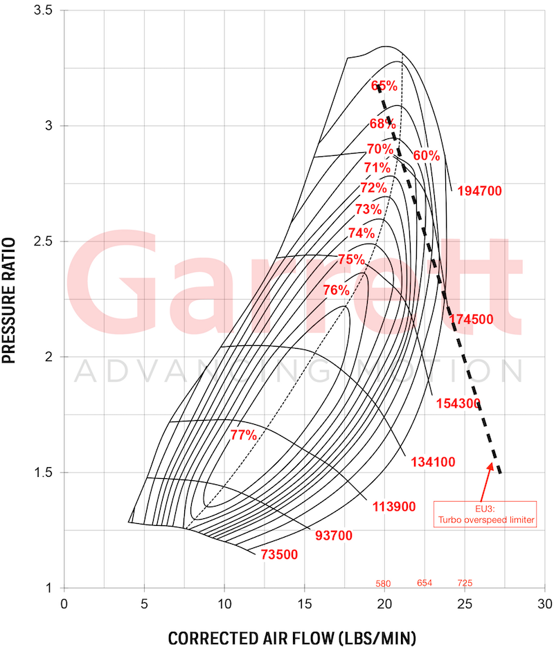
Annotated GT2052 map
Note the figures in red above the x-axis are MAF in kg/hr.

Because this is a calculated parameter the only way to fully assess whether this limiter is actually impacting is to calculate using the above formula from log data.

This can be done with a spreadsheet app or using a calculated field in MegaLogViewerHD.

As a final illustration of the effect of this limiter, I’ll include a small segement of a log from a site donor who was having some major issues with a hybrid turbo and map levels over 250kPa.
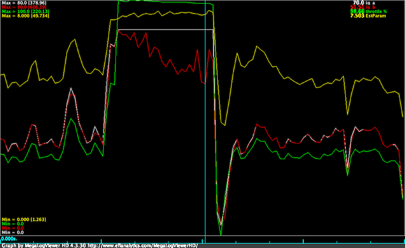
OS Limiter in action

The white trace is request IQ after Driver Demand and Torque/Smoke limiters.
The red trace is the IQ after application of the all system limiters including the Turbo Overspeed map.

The point at the cursor shows a 26% reduction in requested IQ corresponding to the 7.5 cell in the limiter map.

You can also see clearly that as the OS limiter parameter increases above 7.0 the IQ after all limiters reduces. MAP levels when limiting is occurring are around 250-260kPa.

The take away is simple:
If you are running boost above 250 kPa on an EU3 with a "new school" map this limiter is kicking your butt.

Adjusting the limiter

Rather than modifying the limiter table I would suggest altering the tb_speed_const.

  1. Work out max Pressure Ratio at sea level - this MAP divided by AAP $$275kPa / 100kPa = 2.75$$

  2. Subtract that from 7.0 to get your flow component. $$fc = 7.0 - 4.25$$

  3. Work out your maximum MAF multiply and multiply by 0.1738 to get flow rate $$720 \times 0.1738 = 125$$

  4. Divide the flow component by flow rate to find tb_speed_const: $$4.25 / 125 = 0.034$$

A note GT2052S turbo maps

The Garrett catalog and website list three different compressor trims for the stock GT2052S turbo: 48, 50 and 52. There are two maps available for the 52 trim version. The newest of these, which shows an extended range to a pressure ratio of 3.5, is on Garrett website. The others can be found in Garrett catalogs.

The problem here is that the Td5 uses the 54 trim compressor, and there is no publically avaliable map. The 52 trim will be the closest in performance but it will not be the same.

Donor XDFs v3.0

Wednesday, September 11, 2019 - 14:15

This was originally planned as an v2.2 update to the Donor XDFs. I decided the change of filenames and change to 1.60 XDF spec required a bump to 3.0.

XDF naming convention

The naming of previous versions of the XDF’s included both fuel map and variant identifiers.

When there are two variants with the same fuel map the only difference in the fuel map is the name of the variant in fuel map header. For editing purposes this means the required XDF is identical.

To eliminate this duplication the v3.0 XDF’s drop the variant name.

Valid Gear Ratio

The ECU uses engine speed and road speed to determine the currently gear selected.

Manual maps specifically check that the current gear ratio is within +/- 12% of the value defined in the Valid Gear Ratio scalars. If the calculated ratio is outside this range Cruise Control is disabled.

This appears to be the root cause of Cruise Control not functioning on manuals when transfer case ratio swap and tyre sizes are changed by a significant amount.

Fortunately it’s pretty straightforward to determine the value required using the formula:

$$\frac{RoadSpeed \times 1000}{RPM} = gearRatio$$

Verification of formula

To validate the scalar values we can estimate the road speed using the RAVE specifications for top gear, high range in a D2 Td5 Manual.

First calculate the rolling circumference for a 235/70 16 stock wheel.

Section Height: $$235 \times .70 = 164.5mm$$

Rim diameter: $$16 \times 25.4 = 406.5mm$$

Rolling circumference: $$164.5 \times 2 + 406.5 \times \pi = 2310mm = 2.310m$$

Then calculate the speed at 2000rpm.

Speed from gear and rpm: $$\frac{RPM}{(GearRatio \times TransferRatio \times FinalRatio)}\times RollingCirc\times \frac{60}{1000} = speed kph$$

Discovery 2 Td5 Manual, stock top gear: $$\frac{2000}{0.770 \times 1.211 \times 3.538} \times 2.310 \times 0.06 = 84.02kph$$

Based on the estimated road speed of 84kph at 2000rpm, we can now calculate the kph/rpm value.

Gear ratio kph/rpm: $$\frac{84.02 \times 1000}{2000} = 42.01$$

The scalar value used in the stock map for 5th gear is 40.50.

So there seems to be variation between scalar and calculated ratio in each gear:

Gear Calc GR Stock GR Error
1st 8.76 8.00 +9.50%
2nd 15.17 14.10 +7.58%
3rd 23.16 22.00 +5.27%
4th 32.35 30.60 +5.72%
5th 42.01 40.50 +3.70%

I'm not entirely sure of the reason for this discrepancy but keep in mind that the gear ratio has a +/-12% tolerance.

I personally wouldn't calculate these values from ratios and tyre dimensions for real world use. The easiest way to find the correct ratio will be to make a note of RPM and road speed in the gears where you use cruise control.

Ratio0 is reverse, Ratio5 is 5th gear.

Patchers

The MAF and AAP patchers are included in the release.

The AAP patcher has been updated to avoid the previous situation where a stock EU3 map would show as "patched". In this version the standard map always displays as "unpatched".
So for 10P maps the 3 wire AAP setting is "unpatched", and on 15P maps the 4 wire AAP setting is "unpatched".

Applying patches is not entirely obvious:

  • click the "Apply Patch" button
  • click the "Apply" button at the bottom the dialog
  • save the map file from the file menu or save icon

The patches contain the original base data so map can be restored to original settings.

15P Limiters

There are two new limiters for the EU3/15P maps.

I suspect one or both of these are causing problems for most people running big tunes and/or high boost.
These will need posts to explain what the limiters are doing and what you need to consider before touching them. I'll try to get these done over the coming couple of weeks.

Other stuff

Because this release is built on some significant changes - moving from MATLAB and CSV, to Python and SQLite 3 - there is potential for errors to have crept in. I've spent a fair bit of time trying to ensure there is nothing obvious.

However after working on the code and data for the last week I'm sure I have missed obvious things.

Please let me know if you find any issues and I'll rectify for the next update.

XDF updates update

Monday, September 2, 2019 - 14:15

XDF status update

Added scalar editors for:
- Boost scalars (in previous xdfs)
- WGM scalars (in previous xdfs)
- MAF voltage limits (new)
- Gearbox valid ratios (new - should solve CC issues on a Manual Td5 with TC ratio swap )
- EU3 temperature guess (new - informational for turbo speed estimation)

I'm currently working on adding the MAF and AAP patches to the new XDF builder. If all goes to plan I'm hoping to get the v2.2 update on the site in next couple of days.

end update

I've put in some dedicated effort on the XDF builder over the last couple of days and there has been a fair bit of progress.

The work has been mainly to do with the way the XDFs are built - but there should be some visible improvements in the XDFs as a result.

XDF WIP

Things that have been improved include the consistency of axis naming and formatting.
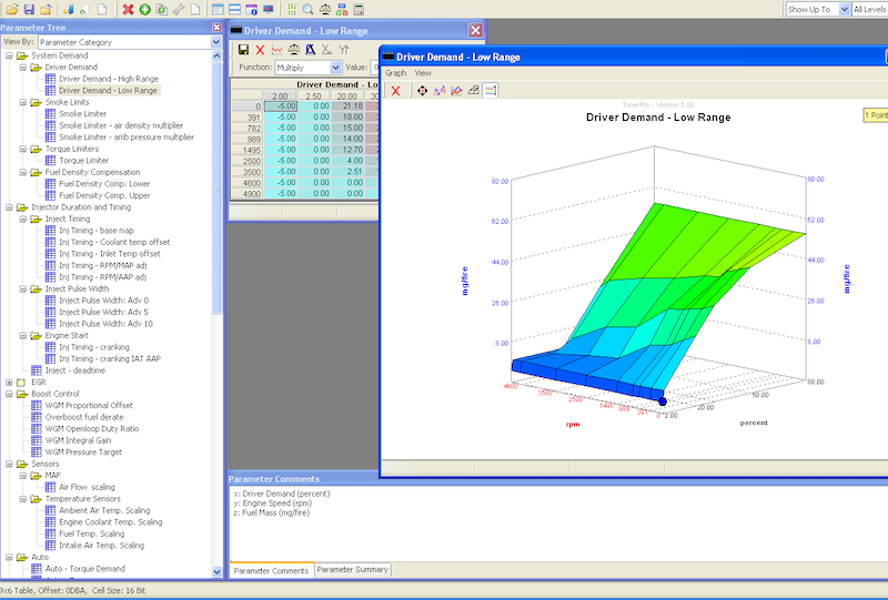
The axis naming on graphs has been reduced to units only. Full naming of the axes now appears in the parameter comments panel and floating tips when you hover over the table name in the side bar.

Category tagging of the tables was added over the last couple of days and I got that working correctly today.

The main outstanding task now is adding the code to insert scalar editors. I still need to add in the MAF and AAP patches but that is lower priority at the moment.

There will be a few additional tables defined but the focus is on getting the main limiters defined for the EU3.

On the MSB front there will be separate XDF's for the second map. The previous strategy was based on the mistaken assumption the two maps had the same basic layout, which wasn't the case. I'm sure this good news for some of the donors who work with the MSB ROW maps.

Update (4 Sept 2019)

The core code for the Scalar editors is getting close to done but in the process I've found a bug with Tuner Pro that messes with the units when min and max values are set.

For the ADC min and max the range needs to be limited to a range of -1 to 1024. The bug causes the editor to start at zero, increase in value to 32767, then flip to -32767 and increase to -1 at the right end of the scale. This has been reported to Mark (TunerPro developer) so there will hopefully be a bug fix by the time the XDF's are ready.

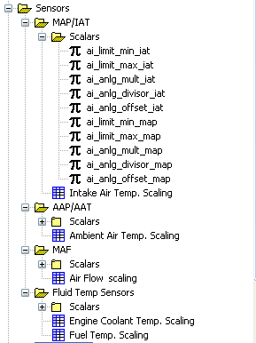
The editors are showing a few of the minor changes that are coming. Sensor settings are now consolidated into physical units - MAP/IAT and AAT/AAP, FT and ECT.

Parameter editors have been include for IAT, AAT, FT and ECT. These new parameter editors are (imo) of very limited practical use so are mainly for informational purposes. I guess there are possibly situations where an alternative AAP/AAT sensor might be required/desired so this will allow for reconfiguration.

Scalar Editors

The ECT/FT editors expose a difference between MSB and NNN ECU's.
On MSB ECU's these sensors have separate ADC inputs.
The NNN multiplexes these two sensors to a single ADC input "mux". This means there is a single MUX scalar editor and changes impact both FT and ECT sensors.

On Td5 map tables

Tuesday, April 23, 2019 - 08:45

How map tables work…

It’s not entirely obvious how the individual tables are used in the Td5 ECU, and I don’t think I’ve explained this anywhere else.

The Basics

All tables are looked up using linear interpolation. This is done by searching along an axis to find the values on each side of the target value.

If the target value is lower than the minimum or higher than the maximum the nearest “edge” is used.

Using a EU3 torque limiter table as an example this would mean an engine speed value of 500 rpm (which would only occur when cranking) would be clamped to the 600 rpm column, while a value of 5500 rpm (possible but unlikely) would be clamped to the 5000 rpm column.

EU3 Torque Limiter

If the target value was within the bounds of the table, say 2400 rpm, the value would determined by finding the axis values immediately above and below - 2200 rpm and 2500 rpm.

The interpolation between column values is done by finding the fraction of the difference between the column values at which the target value falls.

$$\frac{2400 - 2200}{2500 - 2200} = \frac{200}{300} = 0.66666$$

Then the difference between the table value for 2200rpm and 2500rpm is multiplied by the fraction to determine the value off the fraction.

$$(44.25 - 42.53)0.6666 = 1.15$$

And finally the lower column value is added to the fractional value to give the limter value at 2400rpm.

$$42.53 + 1.15 = 43.68$$

Essentially the method assumes there is a straight line (hence the linear) joining the points represented by the x-axis and table values.

Higher Dimensions

The same basic principles are applied to 2 and 3 dimensional tables. With 2 dimensional tables the ECU interpolates on both the x and y axis, with the column and row values representing the four corners of a cell. If you look at the graph view of a 2d table the intersections of grid lines represent cell corners and the flat surfaces that fill the cells are all the possible interpolated values that occur between the corner values.

Two sets of tables are actually 3d tables. These are the fuel temp compensation tables, and the inject duration tables.

With these tables there is a hidden third dimension - rpm in the case of fuel temp, and advance in the case of inject duration.

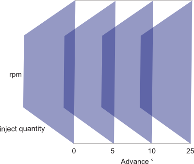
Using the inject duration table as an example, the ECU first determines which tables are above or below the current advance/retard value in the same was as described above. Then the inject duration interpolated from inject quantity and rpm for the maps on either side of the adv/ret value, and the inject duration values are interpolated to find the fractional duration amount.

duration tables as a cube

In effect the duration table is a cube with inject quantity, rpm and advance/retard as the three axes (please excuse the wonky illustration!). The first and last duration tables are sides of the cube, and the remaining table(s) divides the space between the sides equally.

EU2 System Demand Flowchart

Thursday, June 20, 2019 - 12:30

This is the first of what should be a series of posts which provide a little more detail about how the maps fit together.

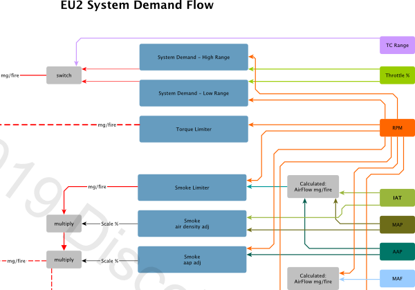
The individual flowcharts are too large to embed while maintaining any kind of legibility so the full content is attached as a pdf at the end of the post.

EU2 System Demand Flowchart

The current flowchart covers the operation of the EU2 "System Demand" (aka Driver Demand) map and Smoke limiter.
"Driver Demand" is used in Land Rover docs to refer to the throttle position - not the maps. Another reason for describing these maps as System Demand is that the Cruise Control controls speed by using a calculated throttle % that substitutes for the "driver demanded" throttle % as the input to the System Demand maps.

The flow chart includes mention of a "new" Braking IQ map - this is currently marked as Map010 for D2, and Map011 for Defender in the NNN XDFs. Note that these maps are effectively disabled in all tunes - the "limit" is set to 100mg/fire so has no effect - but I have included as they are "active" in the sense that if you modify to a point where the values are lower than the smoke limiter the map will alter engine behavior.

Also note that the Manual maps include Autobox code and vice versa, so the Auto Torque reduce checks are used in Defenders and D2 Manuals.
The maps will have no effect, but the checks are there.

There is a scalar which selects between IAT and ECT as the temperature input to the Smoke air density adjust map. I believe this is set to IAT for all tunes so this hasn't been included to keep things simple.

The calculated airflow is discussed in the Airmass post, as MAP Airmass. As discussed in that post the MAF Airmass is calculated but not used as input into the System Demand, Smoke Limiter, or Torque Limiters in EU2 maps.

Cranking IQ, Autobox Torque Reduce IQ and Idle governor IQ calculations are quite complex so are treated a "black boxes" for clarity.

The three final boxes at lower left are parameters that are used in the Torque Limiting routines.

The EU2 Torque Limiter operation will be covered in the next post.

Attached PDF updated 7 April 2019

AttachmentSize
PDF icon EU2 System Demand Flowchart (rev3)221.6 KB

EU3 MAF timeout disable

Tuesday, January 8, 2019 - 10:45

I've had a few requests for details on how to disable the timeout on EU3 maps when the MAF sensor is disconnected.
Without this mod the throttle on EU3 maps is unresponsive for 20-30 seconds when the engine is first started.

It's quite simple to do by altering the MAF "out of range" timeout check from a conditional "if timeout branch" to an unconditional "branch".

You'll need to use a HEX editor for this.

First open up you .map file in your favorite hex editor - I use Hex Fiend on macOS for stuff like this.

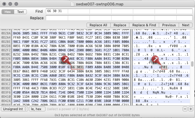
With the .map open search for a sequence of hex bytes: 66 30 31

Unmodified .map

There should be only one occurrence of this sequence in the .map file at an offset of somewhere around 0xD100 - 0xD400.

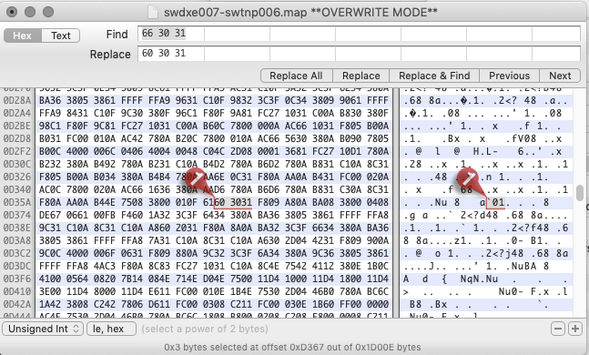
Next, change the 66 to 60 - this alters the conditional branch instruction to an unconditional branch, meaning the ECU always executes the "no MAF" code.

Modifed .map file

Save the modified .map file and you are done.

Be aware that this mod “lobotomizes" the EU3 maps to a EU2 style single smoke map configuration.
The ECU will only use the main high range smoke map (map 60).

This should work for all EU3 variants.
If you can't locate the byte sequence let me know which variant you are working with.

Note: The checksum needs to be updated if you are loading the .map using the Nanocom. This can be done by loading the .map file into Tuner Pro with the appropriate XDF and then saving the "bin". The checksum is updated on save. Td5 Map Editor will also update the checksum. If you are using Td5 ME you'll have to either make and the reverse a change to the map so the file is marked as "dirty" then save, or "save as". Thanks to Neil for mentioning this omission.

Site updates

Tuesday, August 7, 2018 - 21:00

While it shouldn't be obvious, I've moved the website to a new host. The process has been fairly problem free but if anything is acting up let me know.

On a related topic Google Chrome and other browsers have started marking sites that aren't secured will SSL certificates as "not secure". It's really a bit of overkill for a site like this, but as the Not Secure warning is kind of off putting I've moved the site across to the secure protocol.

Chrome is currently still complaining because the images in a lot of the posts are hard coded to the insecure address. I'm slowing working my way through and fixing up the links.

For the moment the front page and the donor login pages are now flagged as "Secure".

Tuner Pro XDF's

Tuesday, August 22, 2017 - 16:00

The donor-ware XDF's for NNN ECU's had a bit of a version bump today...

Note: These XDF's and all future updates are available anyone who supports the site with a donation of $5.00 USD or more.

These are changes I could remember:

Version 2.0 20170822
- Add SOI maps
- Add Smoke compensation maps
Note that EU3 maps use an adjust map and scaling map pair.
The scaling map is a multiplier so if there is 0 in the scaling map the adjust output is 0.
It's going to take me a bit of time to document so please be patient.
Information will be posted when it is ready.
- Add Air Conditioning load map
- Add Auto Torque Reduction IQ map
- Add Auto Engine Torque map
- Alter scalar naming
- Add Waste Gate Modulator control maps and scalars
- Add "hidden" Injector Idle Response map to EU2 XDFs
- other stuff...

There were a few tweaks to improve axis scaling, and descriptions added...
As always the XDF's are a work in progress.

Tuner Pro Update

Mark Mansur has just uploaded a new version of Tuner Pro which fixes a bug introduced in the previous version.
The bug prevented the patches included in the Td5 XDF's from applying.
You can download the new version from the Tuner Pro Download Page.

Overboost Fuel Cut Map

Wednesday, August 2, 2017 - 12:30

The donor XDF's identify a map that limits fuelling when overboost occurs, which I've named "Overboost Fuel Cut".
That naming seems to have created a bit of confusion as I've had a few people email asking if they should increase this map to match the torque limiter.

Where the confusion arises comes from common belief that the kangaroo hopping or jerking that occurs when the wastegate fails to operate is a fuel cut caused by an overboost condition. What is actually occurring is quite different.

Back to the ADC

I've posted previously about the signal flow from MAP sensor through the ECU Hardware to the Analog Digital Conversion module.

This is roughly:

  • Sensor converts pressure to voltage
  • Resistor divider drops voltage by approx 10%
  • ADC converts voltage to a value between 0-1023
  • The value is checked against ADC Max and Min

If the value is above ADC Max, a logged high fault is set, and if below ADC Min a logged low fault is set, and the sensor default value is used.

And this is what occurs when the wastegate fails to open. The pressure quickly increases to a value higher than ADC Max, and the sensor default is set.
Limit checking happens at the first stage of processing after AD conversion, and well before any fuelling calculations. While this might appear to be a fuel cut that is simply a side effect of the dramatic drop in calculated airmass.

The real overboost fuel cut

Overboost Fuel Cut Map is used specifically when the current boost exceeds the boost limit value.
The current boost value is calculated as the difference between Manifold Absolute Pressure (MAP) and Ambient Absolute Pressure (AAP). This is obviously influenced by the pressure drop across the air filter and airbox.

Say for example the reading are 240kpa MAP and 100kpa AAP, in this case boost is 140kpa.
However if there is a 3kpa drop caused by the airfilter, that becomes 240kpa MAP and 97kpa AAP which gives 143kpa boost.

The stock ADC Max limit for the MAP is the equivalent of about 242kpa and stock Boost Limit is set at 142kpa. Due to the drop in AAP at high boost you'll generally reach the Boost Limit at least 2-3kpa before the ADC Max limit.

Once boost exceeds the Boost Limit, the ECU limits the amount of fuel injected using the Overboost Fuel Cut map. This limiting remains in place until the current boost drops below the level set by the Boost Limit Recovery parameter.

A few thoughts

My take on this map is that it is used by the ECU to help control boost levels after overboost is detected, and prior to the MAP value exceeding the maximum limit. With stock values this is a small window of perhaps 3kpa // 0.4psi. It is basically a last ditch effort by the ECU to control overboost, and I personally don't' see any legitimate reason to mod this map.

The best approach is to set boost limit and boost limit recovery values at the maximum value you expect to run.
If this is higher than 150kpa/1.5bar boost you will need to replace the MAP sensor with a wider range unit.
Then adjust the ADC Max value to suit - some thing like 250kpa if you have set the boost limit to 150kpa.
Working in this way you will only hit the Overboost Fuel Cut when the boost reading goes above your maximum expected value.

Pages

randomness