
A couple of months ago I posted on how the Wastegate Modulator operates when energised and de-energised.
That research was necessary because the “common forum wisdom” that the WGM operated to reduce boost seemed to be completely at odds with what the WGM control code appeared to be doing.
To quickly recap, when active the Wastegate Modulator rapidly switches between boost pressure and turbo intake pressure to regulate the pressure at the wastegate actuator. When the Modulator is inactive boost pressure flows directly to the wastegate actuator.
The effect of the switching between intake and boost pressures at 16 times per seconds is to create a blended pressure which related to current value of the two pressures and to the amount of PWM applied. Because the intake is always pressure is always lower than boost pressure (assuming the Turbo is producing boost) the WGM can only reduce pressure at the Wastegate Actuator when there is a PWM signal.
With no PWM modulation applied to the modulator boost pressure flows directly to the wastegate actuator meaning the wastegate behaves as it would if the modulator was not present.
This is absolutely fundamental to the way the WGM maps work, so
if you have any doubts I’d recommend (re)reading the post on WGM operation, and if necessary doing some testing to verify this is correct for yourself.
The WGM Controller
I’ve had a bit of difficulty trying to decide how best to write up the WGM. The software contains support for a full blown PID controller, however the WGM implementation uses only Integral component. The Proportional and Derivative components are both disabled.
For the moment I’ve decided to stick to what is actually used in the standard implementation, but keep there is a huge amount of hidden flexibility and the full PID setup should prove useful for full-blown Boost Controller applications down the track.
As a note of explanation, the parameter names I'm using below come from a list of Td5 System Constants from offical Land Rover engineering docs that were posted to a Spanish forum. While they are not natural language they have the distinct advantage of accurately defining the purpose of the value.
So let’s look at the details.
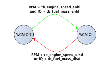
WGM Enable and Disable
The first thing to note is that the Wastegate Modulator is not “always on”. The control code is only enabled when the engine is operating above specific RPM and IQ thresholds.
The enable thresholds are set by two system constants:
- tb_fuel_mass_enbl = 24.00 mg/fire
- tb_engine_speed_enbl = 1900 rpm
Once the fuel mass (IQ) requested is greater than 24mg/fire and engine speed is greater than 1900rpm the Wastegate Modulator controller is switched on. The controller remain in the “on” state until either engine speed or IQ falls below the disable threshold.
The two system constants for the disable threshold are:
- tb_fuel_mass_disd = 20.00 mg/fire
- tb_engine_speed_disd = 1750 rpm
This state diagram illustrates what is occuring. The controller remains in either an on or off state until the conditions required to switch to the other state are met.
These on/off thresholds are confirmed by data logging. I've filtered a log with just under 1000 data points to extract the lines that have a Wastegate Modulator Duty greater than zero, then plotted RPM vs IQ. The colour bar shows the WGM Duty %.
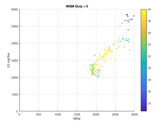
This shows quite clearly the WGM is only active above the operational thresholds described above.
Narrowing the focus to the “off -> on” transition, I’ve selected rows where a 0% WGM Duty is followed by a non-0 WGM duty %.
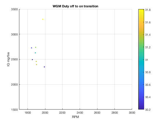
You can see the engine speed values are mainly +/-100 rpm around 1900rpm, and the IQ values appear to be generally above 24mg/fire.
Looking at the “on -> off” transition, I’ve selected all non-0 WGM Duty % values preceeding a 0% WGM Duty.

While the engine speed values are still above 1850rpm, the IQ values between 20 and 24 mg/fire are apparent.
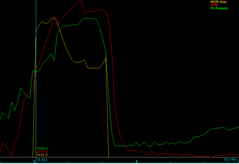
To further illustrate the off -> on transition ploting the log data in more familiar way shows the behaviour of Wastegate Modulator duty, RPM and IQ. In both cases IQ is around 33mg/fire.
The first plot shows behaviour at 1690rpm with IQ of 33mg/fire, and WGM duty at 0%.
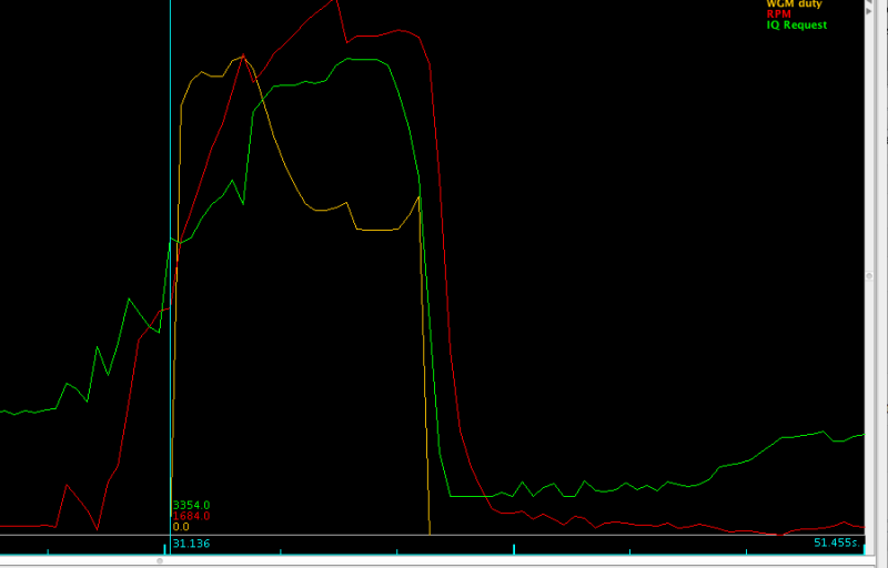
The second data point 290ms later shows engine speed of 1970rpm, with WGM duty at 31%.
Current Boost and Target Boost
These two parameters are calculated each cycle regardless of whether they are used in WGM operation.
Current Boost is a calculated value equal to Manifold Absolute Pressure (MAP) - Ambient Absolute Pressure (AAP).
Target Boost is a value looked up using the final table in all Td5 engine fuel maps.
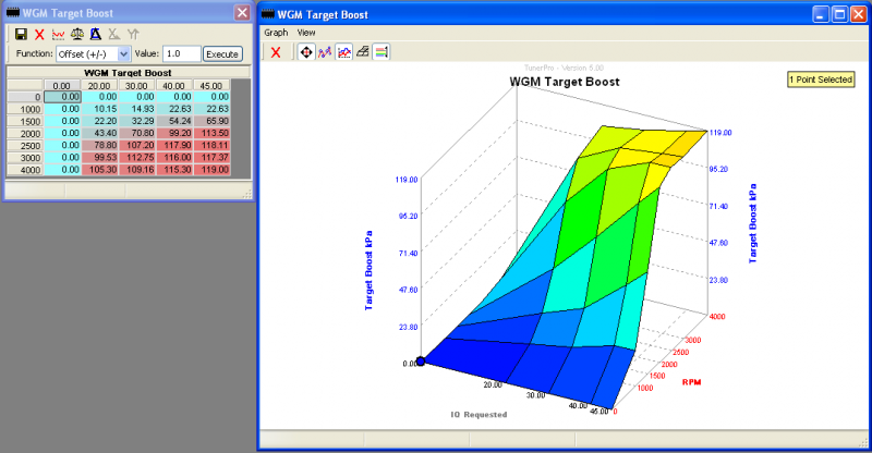
The X-axis value is IQ (or fuel mass) mg/fire and the Y axis is RPM and the Z-value is Target Boost in kPa.
The Target Boost table is identical across Euro, ROW, Japanese and Korean tunes, on Eu2 and Eu3 motors and Manual and Auto D2’s despite the variation in driver demand tables, and smoke and torque limiters which suggests that this table is not precisely controlling the boost to match fuelling.
I’ve highlighted the region where engine speed is above 1750 and the IQ requested is above 20 mg/fire in a stock D2 Auto driver demand map to illustrate the region where the Wastegate Modulator is operating in an unmodified map.
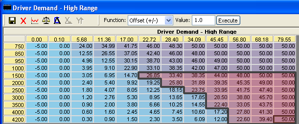
It should be apparent that when you start increasing the duration in the driver demand, smoke and torque limiters that the values returned from the Target Boost table will come from further to the right - in other words the target boost will tend to be higher than for stock driver demand.
Wastegate Modulator Duty Ratio Bias
This map is has Target Boost as the X-axis and RPM as the Y-axis. Z-Axis values are WGM Duty Ratio.
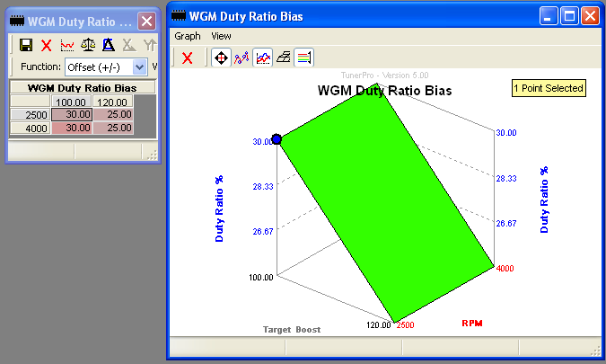
This is the underlying amount of WGM Duty Ratio for a given target boost level. Because the ECU map lookup “clips” axis values to maximum or minimum, anything below 100kPa uses the left column, and anything above 120kPa uses the right hand column.
Adapation to higher boost levels will require modification of the header values.
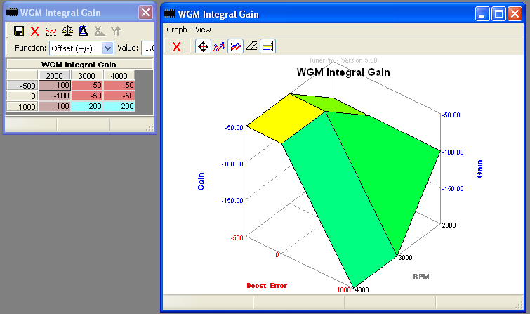
WGM Integral Gain
The Integral Gain map has RPM as the X-axis, Boost Error as the Y-axis, and Integral Gain as the Z-axis.
This is used in the ECU when calculating the Integral (summed value over time) of the error.
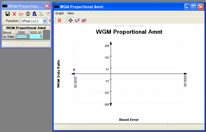
WGM Proportional Amnt
Not Used in factory maps.
X-axis is Boost Error, Y-axis is WGM Duty Ratio.
Boost Error
Boost Error is calculated as the difference between the current boost and the target boost:
Boost Error = Current Boost - Target Boost
Note that if current boost is below target boost the error is negative, and positive if current boost is higher than target boost.
Controller code
The integral map described above should give you a big clue as to what we are dealing with here - a Proportional-Integral-Derivative Controller (PID). This is a type of feedback controller that is widely used to regulate “plant” to a steady state.
Fortunately Land Rover has disabled most of the Proportional and Derivative code so what is left is far simpler. However, the fact all the PID controller is still in place does open up the possibility of some fairly advanced boost control implementations in future. At this point I’ll stick to what is actually used.
Integral Calculation
The WGM controller has a “dead band” of +/- 2kPa which is set by the tb_intgl_enbl. Boost Error values of less than this amount are ignored.
If the Boost Error is greater that +/-2kPa, it is limited to the value set by tb_max_err_intgl which is given as 10kPa, but looks more like it should be 1kPa from my reading of the code. Regardless the constant used has a raw value of 100. Given that the raw boost error figures the constant is applied to are kPa * 100, this has the effect of limiting the max error amount to +/- 1 kPa.
The limited Boost Error is then multiplied by the Integral Gain and then divided by 1000 (raw value) to give the required adjustment to WGM Duty Ratio. You’ll note the Integral Gain table values are all negative, and as previously noted current boost values below target boost result in negative boost error values.
100 * -50 / 1000 = -5
-100 * -200 / 1000 = 20
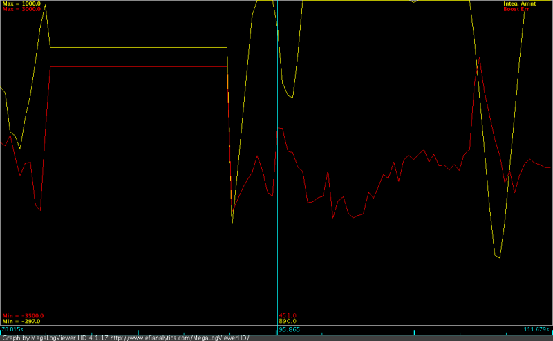
This plot of logged engine data shows how the Boost Error and Integral behave. As Boost Error becomes postive the Integral amount decreases, and vice versa. The other point of note is that the values are not calulated when the WGM is not currently enabled.
The adjustment amount is then added to the accumlated value (Integral) of the Wastegate Duty Ratio adjustment. The maximum adjustment to Duty Ratio is +/-0.2% each time the code is executed.
The WGM controller code runs at 10ms intervals which is set by the scalar tb_intgl_deriv_rate. At this rate the controller can adjust the Duty Ratio by up to 20% in 1 second.
The final step in calculating the Integral is limting checking against tb_clamp_intgl_hi which is set at 10%, and tb_clamp_intgl_lo which is set at -30%.
Total WGM Duty Ratio
The final step is to sum the component values of the PID controller. Because the Proportional and Deriviative amounts are set to zero in this implementaiton this is becomes effectively
Duty Ratio % = Bias + Integral
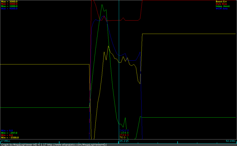
You can see this in practise in this plot of log data.
The Duty Ratio Bias is 25.64%, and the Integral is -1.54% and the total WGM Duty Ratio is 24.1%.
This amount is then checked against tb_max_duty_ratio which is set at 82%, and tb_min_duty_ratio set at 16%.
WGM Module Disable
The WGM module can be disabled by setting the scalar which controls the PWM frequency tb_turbo_pwm_freq to 0. Defenders have a fully configured WGM which only requires setting this scalar to 16 to enable.