
Note link to calculator spreadsheet added at bottom of post
Background
The 1.42 bar boost limitation of the stock Land Rover Td5 engine management system has been a long standing issue when increasing boost levels as a performance upgrade.
The standard solution has been to insert a boost box or some other type of "cheater circuit" in line with the MAP sensor to lower the sensor voltage to provide the ECU with false reading of the boost levels.
In the course of disassembling the ECU firmware it became apparent that the sensor parameters could altered with minor adjustments to the settings in the fuel map to accomodate alternative MAP sensors. The advantage to this approach is that the ECU receives a true reading of the boost pressure rather than a falsified reading that effects pressure readings across the range.
This modification was originally tested on a range of Td5 powered vehicles by members of the Td5Tuning.info forum in January and February 2014.
Under the hood
In order to understand why and how this modification works, it is useful to understand the signal flow from the MAP sensor through the ECU hardware and the processing the ECU firmware applies to the converted analog voltage.
Sensor Signal Flow
The starting point of the conversion process from manifold pressure to ECU representation of the pressure is MAP/IAT sensor which is mounted on the TD5 inlet manifold. The voltage the MAP sensor outputs in response to a given manifold pressure is determined by the characteristics of the sensor used. The relationship between pressure and output voltage is often described as the transfer function of the sensor.
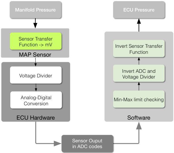
Once the MAP sensor voltage enters the ECU housing it passes through a voltage divider formed by two resistors. The effect of the voltage divider is to reduce the incoming MAP sensor voltage to 90.7% of the original value.
The reduced MAP sensor voltage is then processed by a 10 bit Analog to Digital Convertor (ADC). The 10 bit range of the ADC allows the sensor voltage to be converted to one of 1024 ( 2^10) values. The conversion process is referenced to a 5 volt supply within the ECU, meaning the maximum ADC value of 1023 represents 5000mV and the minimum ADC value of 0 represents 0mV.
At this point the signal flow moves from hardware to pure software. The ECU code first checks that the raw value retrieved from the ADC is within the preset range. Both the minimum and maximum values are related to characteristics of the sensor being used and the range of sensor voltages that are considered within normal range. The maximum value set for the MAP in stock tunes is the equivalent of a pressure reading of 2.42 bar, which will familiar as the point the ECU limits with over boost. Any value that lies outside the initial check range causes an “out of range” fault to be logged.
In the next stage of processing the range checked ADC value is scaled so the converted value is returned to the required units. In the case of the MAP sensor this is millibar * 100. The scaling and offset values reverse the transformations applied by the ADC conversion, voltage divider and the sensor transfer curve to give the pressure value the sensor measured.
Reverse engineering from the stock MAP sensor
At this point we have a basic outline of how the MAP sensor voltage progresses to a digital representation of the pressure, and where intervention is required if we wish to replace a MAP sensor.
To illustrate the process of configuring the ECU values for a specific sensor the following section works from first principles using the stock MAP sensor.
While the explanation of the process may seem long winded and overly detailed the aim here is to explore the underlying assumptions, so that the same procedure can be applied to other sensors.
Hardware
The sensor datasheet
The starting point is to acquire the specification of the MAP sensor as this provides the key information required to accurately configure the ECU. The stock MAP sensor for the Td5 is Bosch part 0 281 002 205, and the key parameters from the data sheet are shown below.
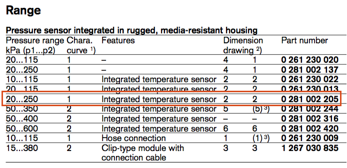
Note that the data table pressure range refers to two points - p1 and p2 The information about these points is given in the plot of the sensor Characteristic Curve.
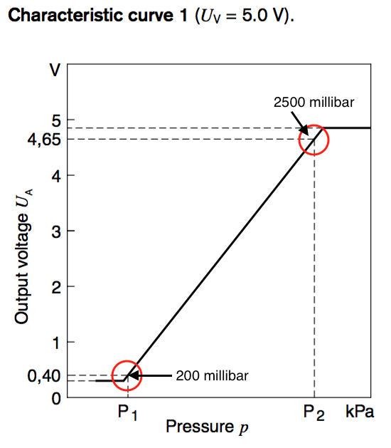
From the spec sheet we can determine that that this sensor has an output of 400mV at 20kPa and 4650mV at 250 kPa.
Sensor Transfer Curve
Calculating the transfer curve is fairly simple and uses only basic high school algebra.
First we calculate the slope of the sensor curve from the two points given by the datasheet.
p1(mV) = 400
p1(kPa) = 20
p2(mV) = 4650
p2(kPa) = 250
The slope of the sensor curve (m) is the change in voltage divided by the change in pressure.
$ m = \frac{p2(mV) - p1(mV)}{p2(kPa) - p1(kPa)} $
Substituting in the stock MAP sensor values
$$ m = \frac{4650- 400}{250 - 20} = \frac{4250}{230} = 18.478260869565217 mV/kPa $$
The slope m tells us that for 1 kPa change in manifold pressure the output of the sensor increases by 18.4783 mV.
The second piece of information required is the voltage the sensor outputs when the pressure is 0 kPa. This is the sensor offset.
 offset = p1(mV) - (m * p1(kPa)
= 400 - (18.4783 * 20)
= 400 - 369.566
= 30.434 mV
The slope (m = 18.4783 mV/kPa) and offset (30.434 mV) provide us with sufficient information about the MAP to configure the ECU.
ECU Hardware
As discussed in the Sensor Signal Flow section the output of the MAP sensor passes through two fixed stages of processing - a voltage divider and the Analog Digital Convertor.
Voltage divider
The Td5 ECU uses a resistor divider arrangement on sensor inputs to provide a form of over voltage protection for the Analog to Voltage Convertor inputs. The divider consists of two resistors:
resistor1 = 121000 ohm
resistor2 = 12400 ohm
$ voltDivider = \frac{121000}{ 121000 + 12400} = 0.9070 $
The divider therefore reduces the sensor voltage to 90.7% of the original value. This means that a sensor output of 5000mV is reduced to 4535mV at the input of the ADC.
ADC Conversion
The 10 bit ADC divides the range of voltages between ground/0mV and the sensor supply voltage/5000mV into 1024 discrete steps.
Dividing the total number of steps by the voltage range gives the step size of 1 millivolt of input voltage. The output of the ADC is a value between 0 and 1023 that represents the measured voltage.
Note that there is debate as to whether n or n-1 steps is correct. Comparing both methods to the ECU curves indicates that n-1 gives the closest match when compared with stock values.
The voltage of each ADC step (or ADC code) is calculated as:
$ step/mV = 1023/5000 = 0.2046 $
Note that it requires a change of at least 4.8876 mV to cause a change of 1 ADC code.
Putting together the hardware scaling factors
The combined effect of the voltage divisor and ADC allows us to calculate the value in "adc codes" the ADC will output for a given sensor voltage at the ECU connector.
 hwScale = ADCstep/mV * voltDivider
 hwScale = 0.2046 * 0.9070 = 0.18557
Using this hardware scaling factor we can calculate the ADC codes produced by a voltage at the ECU MAP input.
For example if we have 4650mV input...
$ adc codes = 4650 * 0.18557 = 862.9 $
This can be extended to calculate the ADC output for a given pressure.
Using 242kPa as an example...
pressure = 242kPa;
adcCodes = ((pressure * sensor slope ) + sensor offset) * hwScale
adcCodes = ((242 * 18.4783) + 30.434) * 0.18557 $
adcCodes = 4502.18  *  0.18557= 835.47 $
As another illustration lets use the sensor maximum of 250kPa...
pressure = 250kPa;
adcCodes = ((pressure * sensor slope ) + sensor offset) * hwScale
adcCodes = ((250 * 18.4783) + 30.434) * 0.18557
adcCodes = 4650  * 0.18557 = 862.9
Error handling
At this point in the process the ECU does error checking against minimum and maximum values defined for the specific sensor input. These are the values that are available as scalar editors (ai_limit_min : MAP and ai_limit_max : MAP) in my "donor-ware" Tuner Pro .XDF's.
If the sensor value in ADC codes is below the minimum the ECU logs "below minimum" and "out of range" faults, if the value is above the maximum, "above maximum" and "out of range" faults are logged.
These are the faults the Nanocom reports as "logged low" (1-2,x), "logged high"(3-4,x) and "current" (5-6,x). "Current" simply indicates that there is either a "logged low" or "logged high" fault set.
Using the stock MAP ADC limit check values as example we can work backwards to find the voltages and pressures that have been set.
min = 93
max = 836
By reversing the transforms performed by the ADC and voltage divisor we can reconstruct the input voltage.
sensorV = ( limits /  mvStepADC ) / vDivider
sensorVmin = ( 93 /  0.2046 ) / 0.9070 =  501
sensorVmax = (836 / 0.2046) / 0.9070 = 4505
So it appears the limits are set to a minimum of 500mV and a maximum of 4500mV.
To find the pressure these voltages correspond to we divide the voltage minus the offset by the mV/kPa value m
$ pressureLimits = (sensor voltage - sensor offset) / m $
$ pressureMin = (501 - 30.434) / 18.4783 = 25.46kPa $
$ pressureMax = (4505 - 30.434) / 18.4783 = 242.15 kPa $
25kPa is well below anything you'd encounter while driving on the surface of this planet but higher than the minimum sensor hardware limit. 242kPa matches the well known stock boost limit.
When recalibrating for a new MAP sensor, or using the stock sensor at higher boost it is essential that these limit values are reset to match the new boost levels and sensor curve.
Software: From ADC codes to pressure readings
Working backwards from ADC codes to pressure is a good warmup for the remaining steps of calculating new multiplier, divisor and offset parameters which makes possible substitution of alternative sensors.
In effect we are reversing the transformations done by the sensor curve m, sensor offset, the voltage divisor and the steps/mV of the ADC process in the same way the limiter pressures were checked.
The value used internally by the ECU for MAP is kPa*100. Additionally the divisor in the stock configuration is set to 1000. This is done due to the integer math used in processing - the multiplier is x1000 to give three decimal places of additional precision, and after the multiplication is completed the result is divided by 1000 to the required two places. This means the multiplier should be multipled by 100000 to bring it to correct units for use in a engine map.
$ multiplier = (1/(m * hwScale ))* 100000 $
$ multiplier = (1/(18.4783 * 0.18557 ))* 100000 $
$ multiplier = (1 / 3.429018) * 100000 = 0.2916287 * 100000 $
$ multiplier = 29163 $
The stock value for this parameter is 29163, so the calculated value is a match for the factory calculations.
Stock divisor parameter is 1000, and reverses the three places precision noted above.
The final parameter is the offset which is the sensor offset calculated in the intial steps converted to ADC codes then scaled by the multiplier and divisor.
$$ offset = \frac{sensor offset * hwScale * multiplier}{divisor} $$
$$ offset = \frac{30.434 * 0.18557 * 29163} {1000} = 164.7 $$
Rounding up to the next highest integer value gives 165.
As noted earlier the offset indicates the voltage the sensor would output at 0kPa pressure. This means that to correct so the sensor curve so the output is 0 mV at 0 kPa you need to subtract the offset if it is positive and add if it is negative.
The ECU math uses addition for this calculation, so if the offset is positive we need to swap the sign to make the number negative. And if the offset is negative the number added needs to be signed swapped to make it a positive number.
So in this case the ECU offset parameter should be -165 to remove the positive offset of 165.
In summary, the values calculated from the datasheet information match the stock parameters:
MAP ADC Maximum: 836
MAP Multiplier: 29163
MAP Divisior: 1000
MAP Offset: -165
Current XDF's have a changed naming scheme for scalars which reflects LR documentation.
ai_limit_max_map  = 836
ai_anlg_mult_map = 29163
ai_anlg_divisor_map = 1000
ai_anlg_offset_map = -165
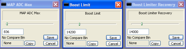
1.5 Bar MAP Recalibration
This is a super simple mod to do!
- Change the MAP ADC Max (ai_limit_max : MAP) value from 836 to 863, which raises maximum input to 250kPa.
- Change the Boost Limit (tb_over_pres_enbl) from 14200 to 15000.
- Change the Boost Limiter Recovery (tb_over_pres_disbl) value to 14800.
This mod uses the stock MAP sensor and does not require any hardware changes.
It's a good choice if you are running stock intercooler and turbo.
In the Tuner Pro .XDF's I give as a "thank you" to donors these parameters can be edited using a simple graphical interface.
The parameters can be located by searching for the stock values using a hex editor of course, so it's your choice.
MAP Setting Calculator
There is now a MAP Parameter calculator on Google Spreadsheets.
It's read only so you'll need to download as an XLSX or ODS spreadsheet (or copy to your Google account) from the File menu.
The spreadsheet contains the values required for the VAG 3 Bar and Bosch 3.5 Bar (PN# 0 281 002 244) sensors.
- Copy the values you need across to the area highlighted in yellow or enter for the sensor you want to use.
- Set the boost limit required (pressure from Point 2 or lower *100). Recovery is calculated as 2kPa below this.
- If the calculated multiplier is greater than 32767 you'll need to lower the divisor. Try 750 as a starter.